


P R O G R AMMI N G A ND S E T T I N G S
373
7.2
MMI (MAN MACHINE INTERFACE)
On the front panel there are eight buttons which allow the user to perform all the settings, reading
and modification operations.
[1]
The adjustment of the settings and the operation mode of the output relays must be performed while
the unit is electrically powered; the alphanumeric display shows the necessary information with re-
ference to the operations performed through the keyboard. The display backlight switches automa-
tically to OFF after a one minute time-out. All preset values are permanently stored in the nonvolatile
memory. The buttons take the following operations:
-
Up
- Move the cursor upwards to the preceding menu options
-
Down
- Move the cursor downwards to the subsequent menu options
-
Left
- Move the cursor upwards to the preceding menu options
-
Right
- Move the cursor downwards to the subsequent menu options
- - Access to the selected menu with the option of modifying any given parameter
- Reset - Reset Command
-
Circuit Breaker Open Command
-
Circuit Breaker Closed Command
- + (modifier key) - 10 Accelerator keys - Pushing for 3 sec. a functional key
display data can be stored and can be recalled when required
- LOCAL/REMOTE - REMOTE Condition Circuit Breaker action (OPEN/CLOSED) is inhibited
- - back to initial function
- - Display LED Label
- - Keyboard lock
- - Escape - stop selected function
At power-up, the display shows the text:
“THYTRONIC
XMR-D-serial number
date and time: (01/01/2000 00:00)
The ON green Led points out the auxiliary power supply voltage (permanent) and possible diagnostic
faults (blink). The display backlight is automatically activated when any key switch is set.
By means of the
(Up) or
(Down) buttons, it is possible to cyclically browse through the menu
options:
READ, SET, COMMUNICATION, TEST
Having identified the sub-menu of interest, it is possible to gain access by using the
(Right) button
and then analogously, run through the relevant options by using the
(Up) or
(Down) buttons.
The full menu tree and some examples are showed in the following pages (numerical values and
settings are pointed out as examples and does not agree with real situations).
—
Reading variables (READ)
All data (measure, settings, parameters, etc...) can be displayed; they are arranged in functional
group submenus:
SELF TEST
>>”
“
SERIAL NUMBER
>>”
“
INFO
>>
”
“
MEASURES
>>
”
“
ACTIVE PROFILE
>>
”
“
PROTECTIONS
>>
”
“
VIN
>>
”
“
VOUT
>>
”
“
RPC
>>
”
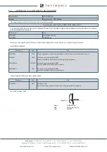
Note 1 Setting changes are enabled when the
Enabling setting by MMI
parameter is set
LED1-1...LED1-16
User Programmable
ON & Diagnostic
Start
Trip
OPEN CB
CLOSED CB
ON & Diagnostic
Start
Trip
LOCAL
REMOTE
f1
÷
f10
Accelerator keys
Display LED Label
LOCAL
REMOTE
VISUAL INDICATION
XMR-D EQUIPMENT MANUAL
Ed. 2.9 - 02/2021


