


FUNCTION CHARACTERISTICS
275
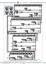
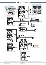
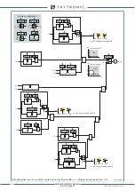
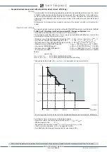
Ground directional overcurrent (67N) - Third element logic diagram (IED>>>) - Projecting operating mode (sheet 2 of 4)
I
E2
I
E2
3V
o
I
E2
&
&
I
EDCLP>>>def
sheet 3
P
A
&
State
I
E2
∙cos
ϕ
≥
I
EDCLP>>>def
I
E
∙cos
ϕ
≥
0
I
ED>>>def
Angle
Semisector
I
E2
∙cos
ϕ
≥
I
ED>>>def
OFF
ON
Insens-Zone
Φ
E
inside trip sector
I
E2
Φ
E
inside trip sector
≥
1
A = ON - Change setting within CLP
A =“ON”
A =“OFF”
A = ON - Change setting within CLP
A =“ON”
A =“OFF”
3V
o
I
E2
I
E
∙cos
ϕ
≥
0
&
&
3V
o
I
E2
TRIP
3V
o
I
E2
TRIP
A = ON - Change setting within CLP
A =“ON”
CLP
A =“OFF”
I
E2
Common configurations
Insens-Zone
OFF
ON
U
E
U
EC
3Votype67N
3V
o
I
I∙cos
Mode67N
≥
M∙threshold
M
Insens-Zone OFF
Insens-Zone ON
3V
o
&
State
U
ED>>>def
≥
M∙U
ED>>>def
3V
o
&
State
U
ED>>>def
≥
U
ED>>>def
3V
o
&
State
U
ED>>>def
≥
U
ED>>>def
I
E2
∙cos
ϕ
≥
M∙I
ED>>>def
I
E2
I
EDCLP>>>def
A
&
State
I
E2
∙cos
ϕ
≥
M∙I
EDCLP>>>def
I
ED>>>def
I
E2
∙cos
ϕ
≥
I
ED>>>def
I
E2
I
EDCLP>>>def
A
&
State
I
E2
∙cos
ϕ
≥
I
EDCLP>>>def
I
ED>>>def
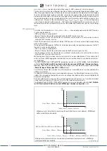
soglia
I
ED
I
E2
Φ
E
o
Φ
EC
Angolo caratteristico
U
E
U
EC
Settore intervento
(direzione linea)
Settore non intervento
(direzione sbarre)
Semiasse caratteristico
Semiampiezza settore
angolare d’intervento
XMR-D EQUIPMENT MANUAL
Ed. 2.9 - 02/2021


