


299
FUNCTION CHARACTERISTICS
Since out of step phenomena characterized by relatively slow time constants, genera-
tor impedance can be parameterized with a value within the range:
X'
d
<Z
B
< 2X'
d
where X'
d
represents generator transient direct axis impedance. The Z
B
value is pro-
grammed in relative value related to Z
nf
.
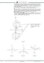
• ZC represents slides discrimination impedance between ZONE A and ZONE B. In order
to understand correctly sliding events inside and outside generator/transformer unit,
this impedance can be parameterized with values within the range:
0,85 Z
CC
< Z
C
< Z
CC
where Z
CC
represents elevator transformer short circuit impedance. The Z
C
value is pro
grammed in relative value related to Z
nf
.
•
ꞵ
represents the angle formed by abscissa axis with straight line passing through R-X
plane origin, where system impedances Z
A
, Z
B
e Z
C
lie (Fig. F), and it is defined as Z
TOT
argument:
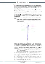
Taking Figure E as reference, the value of the angle
δ
is obtained from the protection
through the trigonometric relationship:
Following additional parameters are programmable by user:
• 78 delta AL (
δ
AL
) = alarm threshold angle. Typically
δ
AL
is programmed for values
between 100°... 110° for 78 protection
• 78 delta TR (
δ
TRIP
) = 78 protection trip angle. Typically
δ
TRIP
is programmed for values
between 80°…90°
• N
A
= Number of External slides in outside generator/transformer group area related to
78 protection intervention. Typically it is programmed with a value of 3 or 4
• N
B
= Number of Internal slides in generator/transformer group related to 78 protection
intervention. Typically it is programmed at value 1
• 78tRES = Sliding counters reset time. If after an out of step event detection no further
events are recorded for 78tRES time, both Zone A and Zone B counters are reset.
The parameter must be defined in consideration of the minimum slip frequency value
(typically 5 s)
• tAl1 Int = ALARM 1 operate time.
• tAl1 RES = ALARM 1 reset time delay
• tA1 RES = ZONE A TRIP holding time (reset time delay)
• tB1 RES = ZONE B TRIP holding time (reset time delay)
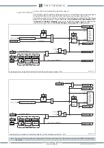
Breaker failure (BF)
Each thresholds (78 TripA, 78 TriB) can be associated to BF (H) and BF (L) protection by activating the
relative parameter in the matrices “Selection of function tripping for BF (H)” or “Selection of function
tripping for BF (L)” in relevant
BF
menus
1
:
• Set \ Profile A (or B) \ Breaker failure - BF side H
• Set \ Profile A (or B) \ Breaker failure - BF side L
78 Logic Block (Block1)
If a logic input is configured with a logic locked function and 78 protection is enabled for this fun-
ction (78-BLK1 = ON), the associated threshold is blocked for a time equal to logic input activation
duration. All sliding counters are disabled in order to start only when block signal disappears. All
mentioned parameters can be set separately during configuration calibration.
78 Functional Blocks
78 Protection can be disabled in following cases:
• Inverse sequence current larger than settable value 78I
2
>
• Direct sequence current lower than settable value 78I
1
<
• The maximum voltage of the three phase to phase voltages larger than settable value
78U>
Note 1 The common settings concerning the Breaker failure protection are adjustable inside the
Breaker Failure - BF
menu.
XMR-D EQUIPMENT MANUAL
Ed. 2.9 - 02/2021


