


368
INSTALLATION
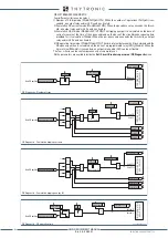
Output relays
The base configuration includes 7 output relays (K1. .. K7) and can be expanded with:
• One board OC1L with 4 output relays (K1-1 ...K1-4)
• One board OC2M with 4 output relays (K2-1 ...K2-4)
• One board XMRI with 16 binary inputs (INM1-1 ... INM1-16) and 8 output relays (KM1-1 ...KM1-8)
• One board XMR16 with 16 output relays (KM1-1 ... KM1-8, KM2-1 .. KM2-8)
It is advisable to verify that the technical characteristic of the contacts be suitable for the applied
load (about current, nominal voltage, make and break current , etc..).
All contacts are shown in de-energized state for standard reference.
In case of connections to power relays coils or contactors, it is
strictly
recommended install pro-
tection devices - like varistors, trapping diodes, etc. - directly on the coils in order to avoid over-
voltage phenomena which can produce disturbances along the cables and/or damage the coils and/or
control relays contacts.
Output Relays
Optional Modules
Output Relays
7 Outputs
S1 IN1F (7 INPUTS)
IN2G (7 INPUTS)
S2 alternately
{
OC2N (4 OUTPUTS)
IN3H (7 INPUTS)
S4 alternately
{
OC1L (4 OUTPUTS)
L1
L2
L3
K1-1
L4
L5
L6
K1-2
L7
L8
K1-3
L9
L10
K1-4
OUTPUT RELA
YS
RELA
Y OUTPUT
E1
E2
K3
E3
E4
K4
E5
E6
K5
E7
E8
K6
E9
E10
K7
D1
D2
D3
K1
D4
D5
D6
K2
BASE
Connector D
Connector E
OC1L
OC2M
XMRI
XMR16
M1
M2
M3
K2-1
M4
M5
M6
K2-2
M7
M8
K2-3
M9
M10
K2-4
OUTPUT RELA
YS
N27
N28
N29
N30
N31
N32
N33
N34
N21
N22
N23
KM1-1
KM1-2
N24
N25
N26
N35
N36
N37
N38
N39
N40
KM1-3
KM1-4
KM1-5
KM1-6
KM1-7
KM1-8
T27
T28
T29
T30
T31
T32
T33
T34
T21
T22
T23
KM2-1
KM2-2
T24
T25
T26
T35
T36
T37
T38
T39
T40
KM2-3
KM2-4
KM2-5
KM2-6
KM2-7
KM2-8
T7
T8
T9
T10
T11
T12
T13
T14
T1
T2
T3
KM1-1
KM1-2
T4
T5
T6
T15
T16
T17
T18
T19
T20
KM1-3
KM1-4
KM1-5
KM1-6
KM1-7
KM1-8
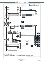
Synchronization
The following time synchronization methods are available:
• NTP protocol (Network Time Protocol) over Ethernet network
• IEC 1588
Local port
A cross cable must be employed.
When used the local port takes priority over the Ethernet port
serial1-sch.ai
RJ45 Connector
WARNING
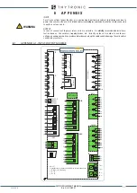
Ethernet ports
XMR-x relays are supplied with two redundant Ethernet ports
[1]
with HW-SW switching command
selectable between TX (RJ45) + FX (optical fibre), with ModBus / TCP or IEC 61850 protocol.
The following variants are available:
• Two TX ports with RJ45 connector for copper network
• Two FX ports for optical fiber network
• One FX + RS485 port
• One TX + RS485 port
• One RS485 port
The connections to the TX port (RJ45) must be made using a category shielded cable FTP Cat.5e or
higher.
Note 1 In normal conditions the primary port is operative, while the secondary is activated only in case of failure of the primary one or with HW-SW
switching command .
Connector TX (RJ45 copper)
Connector FX (Optical Fibre)
RX
TX
Ethernet
RS485
7
6
A+
B-
FTP shielded cable Cat.5e or higher
B-
A+
RS485
Z
1
2
3
4
5
6
7
8
9
10
1
2
3
Y
A
B
NETWORK
X
1
2
3
4
5
6
7
TX
NETWORK
R
FX1
T
R
FX2
T
TX1
NETWORK
TX2
TX+TX
FX+FX
FX+RS485
TX+RS485
RS485 ONLY
R
FX
T
NETWORK
NETWORK
X
1
2
3
4
5
6
7
X
1
2
3
4
5
6
7
X
1
2
3
4
5
6
7
TX
NETWORK
XMR-D EQUIPMENT MANUAL
Ed. 2.9 - 02/2021


