


250
FUNCTION CHARACTERISTICS
elements.
5
The internal selective block of one or more element concerning the directional phase overcurrent
function may be enabled/disabled by means the
IPD>BLK4
,
IPD>>BLK4
,
IPD>>>BLK4
and/
or
IPD>>>>BLK4
parameters (virtual input and output common to all protective thresholds); the
following operating modes are available:
• IN - the element is enabled to receive the selective block from an internal input.
• OUT - the element is enabled to send the selective block to an internal output.
• OFF - the element is disabled to send/receive the internal selective block.
Transmission and reception for the same element is not allowed, so any stall situation due to wrong
setting is avoided.
The internal selective block can work together with an external selective block from other protective
relays (Block2).
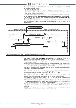
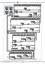
Voltage memory
To increase reliability for three phase short circuits close the VTs, a voltage memory is provided; this
memory voltage is used for reference to detect fault direction when all phase-to-phase voltages are
lower than 1%
U
n
and remains valid for 1 s after voltage collapse.
During the interval a virtual voltage with the same phase and frequency of the previous period to
fault is employed as reference voltage.
Memory-F67.ai
Memory timer
Memory
U
12
Memory
U
23
Memory
U
31
1s
T
0
U
12
U
12
≤
1%
U
n
&
1s
T
0
U
23
≤
1%
U
n
1s
T
0
U
31
U
<
≤
1%
U
n
U
23
U
31
Input U
31
Input U
23
Input U
12
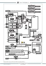
Memory voltage - 67 protection element
U
23
0.01
U
N
Start time
Close on to fault
I
L1
I
L1
* cos
I
PD
>
Start
0.02 s
1 s
1 s (memory voltage)
Voltage reference
(memory voltage)
Example
U
23
,
I
L1
XMR-D EQUIPMENT MANUAL
Ed. 2.9 - 02/2021


