


142
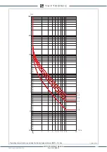
FUNCTION CHARACTERISTICS
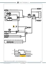
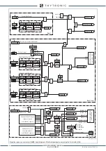
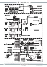
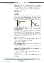
Negative sequence overcurrent (46M) - Logic diagram of the blocking signals concerning the first element (I2>)
Binary input INx
T
0
Logic
INx
t
ON
INx
t
ON
INx
t
OFF
T
0
n.o.
n.c.
INx
t
OFF
Binary input INx
T
0
Logic
INx
t
ON
INx
t
ON
INx
t
OFF
T
0
n.o.
n.c.
INx
t
OFF
Binary input INx
T
0
Logic
INx
t
ON
INx
t
ON
INx
t
OFF
T
0
n.o.
n.c.
INx
t
OFF
Binary input INx
T
0
Logic
INx
t
ON
INx
t
ON
INx
t
OFF
T
0
n.o.
n.c.
INx
t
OFF
Block2 IPh
Block2 IPh/IE
ModeBLIN1
T
0
t
B-Iph
46MS1_BL-diagram.ai
≥
1
≥
1
≥
1
≥
1
t
B-Iph
t
B-IE
BLK1I2>
&
&
BLK2IN I2>
&
&
Enable (ON
≡
Enable)
I2>BLK1
Block2 input enable (ON
≡
Enable)
Pilot wire input
&
I2>BLK2IN
Block1
BLK2IN-Iph
Start
I
2
>
Trip
I
2
>
Iph Block2
IE Block2
BLK2IN-IE
tB timeout
Block2 input
tB-K
tB-L
Block1
FROM ANY PROTECTIONS
FROM PHASE PROTECTIONS
OFF
ON IPh
ON IPh/IE
ON IE
BLIN1
Block1
T
0
t
B-IE
Block2 IE
≥
1
Block1, Block2
TR
IP
PIN
G
M
AT
RIX
(
LE
D+R
EL
AY
S)
≥
1
≥
1
Pilot wire output
TR
IP
PIN
G
M
AT
RIX
(
LE
D+R
EL
AY
S)
ModeBLOUT1
A
B
C
D
BLOUT1
Block2 output
≥
1
t
F-IPh
t
F-IPh/IE
t
F-IE
ST-Iph BLK2
ST-IE BLK2
&
Block2 output
(ON
≡
Enable)
I2>BLK2OUT
Start
I2>
T
0
t
F-IPh/IE
T
0
t
F-IPh
T
0
t
F-IE
BLK2OUT-Iph
BLK2OUT-Iph/IE
BLK2OUT-IE
A = OFF
B = ON IPh
C = ON IPh/IE
D = ON IE
BLK2OUT-IPh-K
BLK2OUT-IPh-L
BLK2OUT-IPh/IE-K
BLK2OUT-IPh/IE-L
BLK2OUT-IE-K
BLK2OUT-IE-L
FROM EARTH FAULT PROTECTIONS
I
2> Block2 OUT
All other BLK2OUT outputs
of phase elements
(see BLK2OUT chapter)
≥
1
All BLK2OUT outputs
of ground elements
(see BLK2OUT chapter)
≥
1
XMR-D EQUIPMENT MANUAL
Ed. 2.9 - 02/2021


