


360
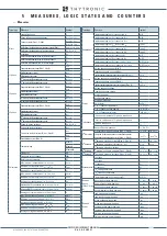
MEASURES, LOGIC STATES AND COUNTERS
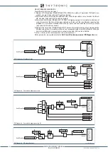
• Digital channels (1...12) allocation (output relay and/or binary inputs).
• Trigger setup; the information storage starts when a state transition on the selected signal occurs.
(protective element start and/or trip, output relay and/or binary input switching).
• Alarm: when the 80% of the buffer space is reached an alarm may be issued. The system being
of linear type, the records are back-to-back recorded to the end of available memory; the alarm
output is a warning in order that the user may download data
[1]
to clear memory for new records
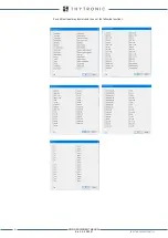
COMTRADE
Records are recorded in COMTRADE format; (Common Format for Transient Data); This is a standard
for the data exchange for various types of tests or simulation datas, etc, for power system applica-
tions.
The measurements are recorded in ASCII or BINARY format. COMTRADE files always come by pairs:
• The “.CFG”-file describing the configuration: number of analog and digital channels, sampling rate,
scale factors, etc.
• The “.DAT”-file containing the data
The COMTRADE is part of IEC 60255-24 standard.
The recording can be analyzed by mean of Thyvisor sw or any other standard compliant viewer.
The record quantity is depending on settings of following parameters:
• Pre-trigger and post-trigger times
• Number of allocated channels.
By means of the following formula the record quantity may be evaluated:
where:
• N
record quantity
• v
i
sampled measures
• v
RMS
analog measures (RMS)
• n
B
logic variables (2 up to 16 variables)
• t
pre
pre-trigger time interval
• t
post
post-trigger time interval
• f
frequency
Example 1
With the following setting:
• Pre-trigger:
0.25 s
• Post-trigger:
0.25 s
• Sampled measures:
i
L1
,
i
L2
,
i
L3
,
i
E
• Analog measures:
I
L1
,
I
L2
,
I
L3
,
I
E
• Logic variables:
KC1-1, KC1-2, KC1-3, KC1-4, KC1-5, KC1-6, IN1-1, IN1-2
up to 180 record can be stored if f = 50 Hz, since
Example 2
With following setting:
• Pre-trigger:
0.5 s
• Post-trigger:
0.5 s
• Sampled data:
i
L1
,
i
L2
,
i
L3
,
i
E
• Analog channels:
I
L1
,
I
L2
,
I
L3
,
I
E
• Digital channels:
KC1-1, KC1-2, KC1-3, KC1-4, KC1-5, KC1-6, IN1-1, IN1-2
up to 75 records can be stored if f = 60 Hz, since
Note 3 Data are stored into non-volatile memory; they are retained once power is turned off
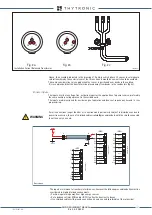
trigger.ai
Disturbance Trigger
Trigger
Time
pre-trigger
post-trigger
N
= int
(34 + 20
v
i
+ 4
v
RMS
+
n
B
)·
12000
(
t
pre
+
t
post
)(s)
·
f
(Hz)
50 (Hz)
= 180
(34 + 20 · 4 + 4 · 4 + 2) · (0.25 + 0.25)
N
= int
12000
· 50 (Hz)
50 (Hz)
= 75
(34 + 20 · 4 + 4 · 4 + 2) · (0.50 + 0.50)
N
= int
12000
· 50 (Hz)
60 (Hz)
XMR-D EQUIPMENT MANUAL
Ed. 2.9 - 02/2021


