


358
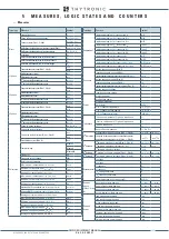
MEASURES, LOGIC STATES AND COUNTERS
—
Protections
For each protection threshold, the following data are available:
• Start
ON/OFF
• Trip
ON/OFF
• Logic block (Block1)
ON/OFF
• Selective block (Block2)
ON/OFF
• Cold Load Pickup
ON/OFF
—
Delayed inputs
The binary input states, acquired downstream the delay timers are available:
• IN1-1
ON/OFF
• IN1-2
ON/OFF
• INx-x
ON/OFF
—
Self test
Proper management (programming and remote monitoring) of the self-diagnosis function ensures
the fast detection of most of the protection system failures and significantly reduces the need for
periodic testing.
Following anomalies (MINOR) are not relevant (the protective elements continue to work):
• Oscillography run-time
OK/NOT OK
• Data Bus minor
OK/NOT OK
• Protection I/O assigned run-time minor
OK/NOT OK
• PLC I/O not-matching run-time minor
OK/NOT OK
Lower level diagnostic (MINOR) can be output or ignored; for this purpose the
MINOR Fail alarm
parameter can be set
ON
or
OFF
inside the
Set \ Self test relay
submenu.
All remaining anomalies
disables all protective functions
[1]
.
The self test information are:
• Protection and controls
ON SERVICE/OUT OF SERVICE
• System diagnostic
OK/NOT OK
• Device diagnostic
OK/NOT OK
• Program diagnostic
OK/NOT OK
• Data-base boot
OK/NOT OK
• Data-base runtime
OK/NOT OK
• DSP boot
OK/NOT OK
• DSP run-time
OK/NOT OK
• Memory boot
OK/NOT OK
• Memory run-time
OK/NOT OK
• Data Bus heavy
OK/NOT OK
• PLC boot
OK/NOT OK
• PLC run-time
OK/NOT OK
• Protection I/O assigned verify startup
OK/NOT OK
• Protection I/O assigned verify run-time major
OK/NOT OK
• Total protection I/O assigned not-matching
0
• Protection I/O assigned not-matching
• PLC I/O assigned not-matching
OK/NOT OK
• PLC I/O assigned not-matching run-time major
OK/NOT OK
• Total PLC I/O assigned not-matching
0
• PLC I/O assigned not-matching
Note 1 The relays are being switched in rest position (ON if set with Energized logic - OFF if set with De-energized logic)
Typology
Measure
Symbol
Energy
Positive active energy
E
A
+
Negative active energy
E
A
-
Total active energy
E
A
Positive reactive energy
E
Q
+
Negative reactive energy
E
Q
-
Total reactive energy
E
Q
78 Function
Impedance
ZN
Resistive component impedance
RN
Reactive component impedance
XN
CosPhi impedance
CosPhi
78 Angle
Delta
Frequecy rate of change angle
fDelta
Discrimination threshold zone A/B
Zone
Zone A number of transition
NA
Zone B number of transition
NB
PT100
Temperature Pt1...Pt8
T1...T8
XMR-D EQUIPMENT MANUAL
Ed. 2.9 - 02/2021


