


FUNCTION CHARACTERISTICS
239
The current stabilization thus depends on the residual current values as well on the their displace-
ment angle
.
Three operating conditions with ideal and matched measurement CTs (pE1 = +1 and ME
(H)
=1) are
considered:
• Earth fault inside the protected zone, powered only from the starpoint
The trip current is equal to
I
E1
while, being
I
E(H)
= 0, the stabilization current is:
I
ES
= 4 · (
I
E1
-
I
E1
) = 0
The element trips when the fault current exceeds the minimum threshold set
I
REF
> (maximum sen-
sitivity for internal fault).
• Earth fault inside the protected zone, powered from both sides
The trip current is
I
E1
while, assuming that
I
ECH
has the same module and is in phase (
= 0 °) with
I
E1
, the stabilizing current is:
I
ES
= 4 · (|
I
E1
-
I
E1
| - |
I
E1
+
I
E1
|) = - 8
I
E1
< 0 =>
I
ES
= 0
Since
I
ES
is zero the element trips when the fault current exceeds the minimum threshold set
I
REF
>
(maximum sensitivity for internal earth fault).
• Earth fault outside the protected zone (external fault)
The trip current is still equal to
I
E1
, while being ideally
I
ECH
= -
I
E1
(residual current on the starpoint
grounding out of phase with the phase side H residual current, i.e
= 180 °), the stabilization cur-
rent is:
I
ES
= 4 · (|
I
E1
+
I
E1
| - |
I
E1
-
I
E1
|) = 8
I
E1
that being positive and equal to eight times the trip-
ping current, determines the stabilization external fault protection on increasing to infinity the trip
threshold (maximum stability for external earth fault). If any CT is saturated, a displacement angle
<180 ° is introduced, so the stabilization current is decreased.
In particular, the maximum stability on external fault is obtained with
≥ 100 °. Conversely for
≤
90°, the stabilization current is cleared so the maximum sensitivity is achieved.
For
increasing from 90 ° to 100 ° the sensitivity decreases from
I
REF
> to infinity.
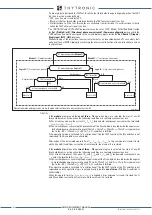
The start of the 64REF threshold becomes active when the following condition are contemporane-
ously active:
A) I
ES(H)
≤
4 ·
I
REF(H)
>
B) I
E1
≥
I
ES
+ [I
REF
>/[1-(I
ES
/4 · I
REF
>)
20
] or in normalized form:
[
I
E1
/
I
REF
>] ≥ [
I
ES
/
I
REF
>] + [1 /[1-(
I
ES
/(4 ·
I
REF
>)
20
]
C) 64REF Enable
= ON
D) 64REF-BLK1
= OFF
where:
• 64REF Enable
is the enabling parameter of the 64REF
• I
REF
> is the minimum threshold setting (max sensitivity) of the 64REF element
• 64REF-BLK1
is the output logic state for the logic block function of the 64REF element.
After expiry of the associated delay time (
t
REF
>) a trip command is issued ; if instead the A), B), C) and
D) conditions current don’t remain valid, the element it is restored.
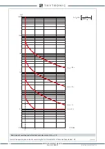
The restricted ground fault protection is then stabilized against external faults by increasing the
threshold of residual current measured at the grounding of the neutral current with increasing stabi-
lization in accordance with the following characteristics:
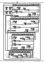
Breaker failure (BF)
Each thresholds can be associated to BF (H) and BF (L) protection by activating the relative parame-
ter in the matrices “Selection of function tripping for BF (H)” or “Selection of function tripping for BF
I
E1
-I
ECH
I
ES
/4
I
E1
-I
ECH
I
E1
+
I
ECH
I
ECH
NO TRIP
TRIP
I
ES
/I
REF
>
I
E
/I
REF
>
0.5
1
1
0
2
3
4
5
6
7
8
9
10
2
3
4
5
1.5
2.5
3.5
4.5
XMR-D EQUIPMENT MANUAL
Ed. 2.9 - 02/2021


