


FUNCTION CHARACTERISTICS
85
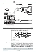
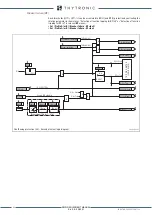
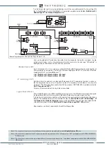
Underimpedance logic diagram (21) - First element
IPh Block2
IPh/IE Block2
T
0
t
B-Iph
Fun-21_S1.ai
I
L1L
U
12
Z
12
=
U
12
/
I
L1L
U
12
≥1%
U
n
I
L1L
≥
5%
I
nL
&
&
&
≥
1
Z<
I
L2L
U
23
Z
23
=
U
12
/
I
L1L
U
23
≥1%
U
n
I
L2L
≥
5%
I
nL
t
Z<RES
T
0
RESET
t
Z
<
0
T
≥
1
≥
1
≥
1
≥
1
≥
1
≥
1
≥
1
t
Z
<
t
B-Iph
t
F-Iph
t
F-all
t
F-IE
t
B-IE
t
Z<RES
Z< Start
Z< Trip
Iph Block2 Start
F21S1 Block3
IF Start
74VT Block
VT fault (74VT)
from Z<< element (ON
≡
Inhibit)
Z< inhibition
Z< Block1
Z< Block2
&
&
&
&
Enable (ON
≡
Enable)
Block1 input (ON
≡
Block)
Block1
Block2 input enable (ON
≡
Enable)
&
&
Block2 IN
Block2 output enable (ON
≡
Enable)
Block2 OUT
Block1
(=0 without fault)
=0 if 20≤f≤70 Hz
Z
< Start
Z
< Start
Z
< Trip
Z< Trip
T
0
t
F-all
T
0
t
F-Iph
T
0
t
F-IE
Z
< Block2 OUT
Z
< Block2 OUT
Iph block2 output
Iph/IE block2 output
IE block2 output
Z
< Start
IPh Block2 input
IPh Block2
IE Block2 input
Block2 IN diagnostic
Block2 output
Block2 input
FROM EARTH FAULT PROTECTIONS
FROM ANY PROTECTIONS
FROM OVERCURRENT PROTECTIONS
Block1
T
0
t
B-IE
IE Block2
Z
12
≤ Z
<
Z<
Z
23
≤ Z
<
IPh/IE Block2
IE Block2
I
L3L
U
31
Z
31
=
U
12
/
I
L1L
U
31
≥1%
U
n
I
L3L
≥
5%
I
nL
Z<
Z
31
≤ Z
<
TR
IP
PI
NG M
AT
RI
X
(LE
D+R
EL
AY
S)
Iph block2 output
Iph block2 Start
Block2 IN diagnostic
Iph/IE block2 output
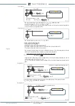
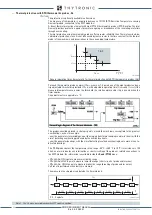
Binary input INx (x=1...8-16)
T
0
Logic
INx
t
ON
INx
t
ON
INx
t
OFF
T
0
n.o.
n.c.
INx
t
OFF
Binary input INx (x=1...8-16)
T
0
Logic
INx
t
ON
INx
t
ON
INx
t
OFF
T
0
n.o.
n.c.
INx
t
OFF
Binary input INx (x=1...8-16)
T
0
Logic
INx
t
ON
INx
t
ON
INx
t
OFF
T
0
n.o.
n.c.
INx
t
OFF
Binary input INx (x=1...8-16)
T
0
Logic
INx
t
ON
INx
t
ON
INx
t
OFF
T
0
n.o.
n.c.
INx
t
OFF
All other BLK2OUT
outputs
of phase elements
(BLK2OUT chapter)
≥
1
All other BLK2OUT
outputs
of ground elements
(BLK2OUT chapter)
≥
1
XMR-D EQUIPMENT MANUAL
Ed. 2.9 - 02/2021


