


292
FUNCTION CHARACTERISTICS
Fun_67NCS1-3.ai
ON
≡
Enable IEDC> directional earth fault
&
A
B
Non-directional
(from 74VT)
Non-directional
A = Directional B = Non-directional
IEDC> Enable
≥
1
CB-State
Block1, Block2, Block4
T
0
t
CLP>
IEDCCLP>Mode
t
EDCCLP>
A
B
C
A =“1”
A =“0 or OFF”
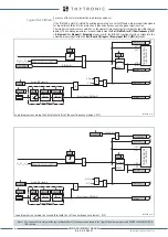
IEDC> overcurrent directional element 67N(Comp) block diagram (sheet 4)
A = ON - Change setting within CLP
B = OFF - CLP disabled
C = ON - Element blocking within CLP
≥
1
CLP IEDC>
I
EC
I
EDCCLP>def
≥
I
EDCCLP
>def
&
State
≥
I
EDC>def
I
EDC>def
Block by 74VT
(ON
≡
Block)
Internal or external
OFF
74VT
74VTint/ext67NC
t
ED>RES
T
0
RESET
t
EDC>def/inv
0
T
t
EDC>RES
Start IEDC>
Trip IEDC>
TR
IP
PI
NG M
AT
RI
X
(LE
D+R
EL
AY
S)
I
EDC>
Curve
0
T
IEDC>TR-K
IEC>TR-L
IEDC>ST-L
IEDC>ST-K
t
EDC>def
t
EDC>inv
A
B
(sheet 1)
D =“modulo”
Mode67NC
C
D
D =“modulo” C =“proiezione”
C
D
M
(sheet 2)
C =“proiezione”
Common configurations
I
I∙cos
3Votype67NC
IECtype67NC
U
E
U
EC
I
ECH
I
ECL
67N(Comp)
I
L1H
,
I
L2H
,
I
L3H
I
L1L
,
I
L2L
,
I
L3L
Mode67NC
3V
o
Insens-Zone
OFF
ON
≥
M∙threshold
M
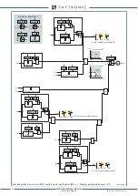
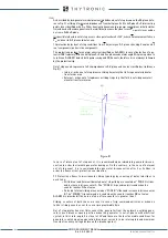
Ground directional overcurrent (67NC) - First element logic diagram (IEDC>) (sheet 3 of 4)
XMR-D EQUIPMENT MANUAL
Ed. 2.9 - 02/2021


