


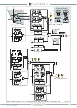


FUNCTION CHARACTERISTICS
259
—
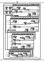
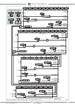
Ground directional overcurrent - 67N
Preface
Four operation thresholds, independently adjustable with adjustable delay.
Each element can be enabled or disabled.
The first two may be programmed with definite or inverse time according the IEC and ANSI/IEEE
standard, as well as with rectifier, EM curve.
The third and fourth thresholds with independent time.
The residual current is measured at
I
E2
input, while the residual voltage can be selected as the
value measured
U
E
or calculated
U
EC
.
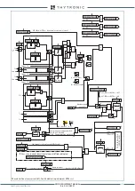
Operation and settings
The first and second threshold may be programmed with definite or inverse time according the fol-
lowing characteristic curves:
• Standard Inverse Time (IEC 255-3/BS142 type A or SIT):
t
= 0.14 ·
t
ED
>
inv
/ [(
I
ED
/
I
ED
>
inv
)
0.02
- 1]
• Very Inverse Time (IEC 255-3/BS142 type B or VIT):
t
= 13.5 ·
t
ED
>
inv
/ [(
I
PD
/
I
ED
>
inv
) - 1]
• Extremely Inverse Time (IEC 255-3/BS142 type C or EIT):
t
= 80 ·
t
PD
>
inv
/ [(
I
ED
/
I
ED
>
inv
)
2
- 1]
• Moderately Inverse (ANSI/IEEE type MI):
t
=
t
ED
>
inv
· {0.01 / [(
I
ED
/
I
ED
>
inv
)
0.02
- 1] + 0.023}
• Very Inverse (ANSI/IEEE type VI):
t
=
t
ED
>
inv
· {3.922 / [(
I
ED
/
I
ED
>
inv
)
2
- 1] + 0.098}
• Extremely Inverse (ANSI/IEEE type EI):
t
=
t
ED
>
inv
· {5.64 / [(
I
ED
/
I
ED
>
inv
)
2
- 1] + 0.024}
• Electromechanical (EM):
t
=
t
ED
>
inv
· {0.28 / [-0236 · (
I
ED
/
I
ED
>
inv
)
-1
+ 0.339]}
Where:
t
:
operate time
I
ED
>
inv
:
first and second threshold setting (
I
ED>inv,
I
ED>>inv
)
t
ED
>
inv
:
first and second threshold operate time setting (
t
PD>inv,
t
PD>>inv
)
Third and fourth threshold (
I
ED>>>def,
I
ED>>>>def
) with definite time.
For all inverse time characteristics, following data applies:
• Asymptotic reference value (minimum pickup value): 1.1
I
ED
> or
I
ED
>>
• Minimum operate time: 0.1
s
• Range where the equation is valid:
[1]
1.1 ≤
I
ED
/
I
ED
>
inv
(or
I
ED
>>
inv
) ≤ 20
• If
I
ED
>
inv
(or
I
ED
>>
inv
) pickup ≥ 0.5
I
En2
, the upper limit is 10
I
En2
• For all definite time elements the upper limit for measuring is 10
I
En2
.
Note 1 When the input value is more than 20 times the set point , the operate time is limited to the value corresponding to 20 times the set point
I
ED
I
ED
>>
I
ED
>>>
I
ED
>>>>
t
ED
>
t
ED
>>
t
ED
>>>
t
ED
>>>>
I
ED
>
t
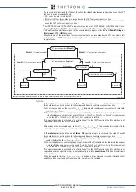
General operation time characteristic for the ground directional overcurrent elements - 67N
TRIP
XMR-D EQUIPMENT MANUAL
Ed. 2.9 - 02/2021


