


220
FUNCTION CHARACTERISTICS
• If the CB position control is enabled (
CB-55 = ON
available inside the
Set \ Profile A(o B) \ Mi-
nimum power factor - 55 \
Cphi< Element \ Setpoints
menu) the start is issued when the following
conditions are meet:
1)
cos
f
<
cos
f
lag
< with Q ≥ 0 or
cos
f
<
cos
f
lead
< with Q < 0
2) Circuit Breaker closed
3) The
t
ARM-cos
f
<
timer (started when CB closes) is elapsed
• If the CB position control is disabled (
CB-55 = OFF
) the start is issued when the following con-
dition is meet:
1)
cos
f
<
cos
f
lag
< with Q ≥ 0 or
cos
f
<
cos
f
lead
< with Q < 0
After expiry of the associated operate time (
t
CPhi1<
,
t
CPhi2<
) a trip command is issued; if instead the
power factor exceed the threshold, the element is restored.
Breaker failure (BF)
Each thresholds (Cphi1<, Cphi2<) can be associated to BF (H) and BF (L) protection by activating the
relative parameter in the matrices “Selection of function tripping for BF (H)” or “Selection of function
tripping for BF (L)” in relevant
BF
menus
[1]
:
• Set \ Profile A (or B) \ Breaker failure - BF side H
• Set \ Profile A (or B) \ Breaker failure - BF side L
Logical block (Block1)
If the
CPhi1<BLK1
and/or
CPhi1<BLK1
enabling parameters are set to
ON
and a binary input is
designed for logical block (Block1), the concerning element is blocked off whenever the given input
is active.
[2]
The enabling parameter is available inside the
Set \ Profile A(o B) \ Minimum power
factor - 55 \
Cphi1< Element, Cphi2< Element \ Setpoints
menus, while the
Block1
function must be
assigned to the selected binary input inside the
Set \ Board 1(2) inputs \ Binary input IN1-1...(IN1-x)
menus.
All the named parameters can be set separately for
Profile A
and
Profile B
.
Note 1 The common settings concerning the Breaker failure protection are adjustable inside the
Breaker Failure - BF
menu.
Note 2 The exhaustive treatment of the logical block (Block 1) function may be found in the “Logic Block” paragraph inside
CONTROL AND MONITOR-
ING
section
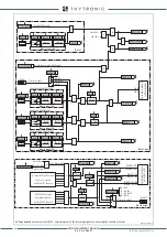
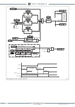
all-F55.ai
General logic diagram of the minimum power factor element - 55
CPhi1< Enable
55 Element - first threshold
Common
Start CPhi1<
Trip CPhi1<
Trip CPhi1<
Block1
BLK1
CPhi1<
&
CPhi1<BLK1
&
cos
ϕ
CPhi1<
t
CPhi1
<
t
ARM-CPhi<
CB
CB Closed
&
CB-55
t
ARM-CPhi<
CPhi1<
DIR
CPhi2< Enable
55 Element - second threshold
Start CPhi2<
Trip CPhi2<
Trip CPhi2<
Block1
BLK1
CPhi2<
&
CPhi2<BLK1
&
cos
ϕ
CPhi2<
t
CPhi2
<
CPhi2<
DIR
XMR-D EQUIPMENT MANUAL
Ed. 2.9 - 02/2021


