


343
—
Second Harmonic Restraint - 2ndh-REST
Preface
When a power transformer is energized, as well know an inrush current flow in the side that have
been energized with an amount and duration that depend by many factors which:
• Instantaneous value of the supply voltage at the time where the transformer is energized
• Transformer design, magnetization characteristic and size
• Residual flux
The maximum amount of the inrush current is produced by energizing the transformer at the zero
point of the voltage wave, when it increase or decrease with the residual flux respectively positive
or negative. Moreover the ratio between the maximum amount of the inrush current and the nominal
current of the transformer decrease if the size of transformer increase, whereas the duration of the
inrush current increase with the size of transformer.
Some types of instantaneous protections as overcurrent, residually connected ground fault and dif-
ferentials, are affected by this inrush current and their unwanted tripping can occur on transformer
energizing.
The second harmonic restraint is available to restraint any selected threshold of NA80 protective
relay:
• Thermal image - 49
• Phase overcurrent - 50/51
• Residual overcurrent - 50N/51N
• Directional phase overcurrent - 67
Moreover one or more output contacts may be allocated to the 2NDH-REST function in order to block
any external protection relays where second harmonic restraint is not available.
Operation and settings
Each second harmonic component of phase currents (
I
L1-2nd
,
I
L2-2nd
,
I
L3-2nd
) is compared with the
I
2ndh>
adjustable threshold.
When one or more currents overcome the setting threshold a start is issued.
The start may be employed to block-off one or more 50/51/50N/51N elements or to block-off external
protections by means output relays (this can be usefully used in order to restraint external protection
relays where second harmonic restraint is not available).
For the purpose to keep in block state the selected elements, an adjustable
t
2ndh>RES
reset delay is
provided.
The setting of
I2ndh>
and
t2ndh>RE
S parameters are available inside the
Set \ Profile A(B) \
Second Harmonic Restraint
menu.
The second harmonic element may be enabled or disabled; to enable it, the
I2ndh> Enable
para-
meter must be set to
ON
inside the
Set \ Profile A(B) \ Second Harmonic Restraint
menus.
All the parameters can be set separately for
Profile A
and
Profile B
.
The output may be assigned to the selected
I2ndh>-ST-K
output relays inside the
Set \ Profile A(B) \ Second Harmonic Restraint
submenu; the same for addressing the LED indicators
(
I2ndh>-ST-L
).
When output relays are programmed for second harmonic element output, the
t
TR
time delays must
reset to zero; the operation mode must be set with self reset (
No-latched
inside
Set \ Relays
subme-
nu) and the
Logic
parameters (
Energized
/
De-energized
) must be programmed in the same way of
the related binary input connected with-it.
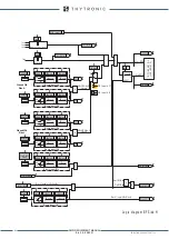
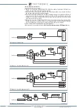
2NDH-REST-diagram.ai
I
L1-nd
t
2ndh>RES
T
0
≥
1
t
2ndh>RES
Start I2ndh>
ON
≡
Enable
I2ndh> Enable
&
I2ndh>ST-K
I2ndh>ST-L
I
2ndh>
I
L1-nd
≥
I
2ndh>
I
L2-nd
I
L2-nd
≥
I
2ndh>
I
L3-nd
I
L3-nd
≥
I
2ndh>
TR
IP
PIN
G
M
AT
RIX
(
LE
D+R
EL
AY
S)
Logic diagram concerning the second harmonic restraint function - 2NDH/REST
XMR-D EQUIPMENT MANUAL
Ed. 2.9 - 02/2021


