


82
FUNCTION CHARACTERISTICS
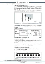
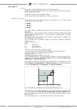
Both thresholds have a operating characteristic circular in plan R, X with definite time curve.
The operating characteristic is a circle with its center located in the source impedance of the plan.
The element trips when the representative point of the calculated impedance is inside the circle
corresponding to the threshold set.
Both underimpedance elements may be enabled or disabled by setting
ON
or
OFF
the
State
para-
meter inside the
Set \ Profile A or B \ Underimpedance-21 \
Z< (Z<<) Element \Definite time
).
The first threshold trip may be inhibited by start of the second threshold by setting
ON
the
Z<disby
Z<<
parameter available inside the
Set \ Profile A or B \ Underimpedance-21 \
Z< (Z<<) Element \
Setpoints
menu.
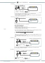
The elements are enabled in the 20 Hz ... 70 frequency range for each phase, if the corresponding
phase voltage is greater than 1%
U
n
and the current is greater than 5%
I
n
.
Since the impedance calculation for the three independent phases, a possible inhibition on stage
has no effect on the rest.
t-int-F21.ai
Z
Z
<<
Z
<
t
Z
<<
t
t
Z
<
TRIP
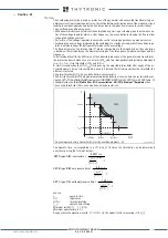
General operation time characteristic curve for the underimpedance element - 21
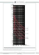
F21_char.ai
X (p.u.
Z
N
)
R (p.u.
Z
N
)
0.5 1.0
Z
<
Z
<<
2.0
3.0
TRIP
TRIP
NO TRIP
R,X operatingcharacteristic of the impedance protection - 21
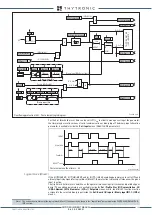
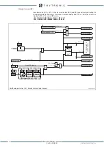
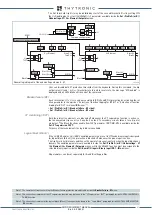
General logic diagram of the underimpedance elements - 21
all-F21.ai
Z
ON=inhibit
2nd Pickup Element
1st Pickup Element
Block1
Block1
Z
Block 2
Block 2
Block3
Block1
Block 2
Block3
&
Block1
Block 2
State
State
Z
<<
def
t
Z
<<
def
t
Z<<RES
Z<disbyZ<<
Z
<
def
t
Z
<
def
t
Z<RES
Z< inhibition
Z
< Start
Z< Trip
Z<
< Start
Z<
< Start
Z<< Trip
XMR-D EQUIPMENT MANUAL
Ed. 2.9 - 02/2021


