


196
FUNCTION CHARACTERISTICS
—
Locked rotor- 50S/51LR(48)/14
Preface
This function ensures protection against the destructive effects of thermal origin in the event of:
• too slow starting or locked rotor during starting - 51LR (48),
• rotor locking during normal operation (after starting) - 50S (stalling),
with eventual speed control - 14, the latter to be employed for motors where the blocked rotor al-
lowed maximum time is less than the starting time (eg. motors with high inertia loads).
Two adjustable operation thresholds, (
I
LR
>
inv
,
I
LR
>>
def
) with adjustable delay (
t
LR
>
inv
,
t
LR
>>
def
), the
first with inverse time and the second with definite time characteristic.
The full protection (locked rotor and too long starting following voltage drops during the start time) is
assured with inverse time characteristic.
Operation and settings
Each phase fundamental frequency current of side L (
I
L1L
,
I
L2L
,
I
L3L
) is compared with the setting va-
lue. Currents above the associated pickup value are detected and a start is issued. After expiry of the
associated operate time a trip command is issued; if instead the current drops below the threshold,
the element is restored.
The start of the inverse time element becomes active (START) when the
I
LR
>
inv
threshold is overco-
me
;
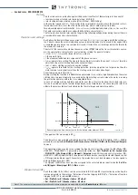
the operate time characteristic is calculated according the general formula:
t
= (
I
MOT-ST
/
I
)
2
∙
t
LR>inv
with
I
larger than
I
LR
>
inv
where:
• t
: the operate time,
• I
: the maximum fundamental component of the phase currents,
• t
LR>inv
: operate time setting. The operate time setting is related to the current
I
=
I
MOT-ST
(must be
adjusted to the motor starting time with nominal voltage).
• I
MOT-ST
: motor starting current with nominal voltage.
• I
LR
>
inv
: operate threshold for the starting detection, (must be adjusted to a larger value than the
motor nominal current but lower than the starting current at reduced voltage).
The minimum operate time is 0.1 s.
During starting the function is inhibited for an adjustable
t
LRCLP
>> time, slightly higher than the motor
starting time, to prevent operations caused by the high starting currents; when the motor is running
the protection operates within the
t
LR
>> adjustable time.
In case of starting with locked rotor and motor near the critical overheating, the locked rotor pro-
tection is carried out by the thermal image because the temperature rise caused by the rotor lock
adds to the previous thermal load stored by the thermal image and operates quickly.
The upper limit for measuring is 50
I
nL
.
The elements can be enabled or disabled by setting
ON
or
OFF
the
ILR> Enable, ILR>> Enable
parameters inside the
Set \ Profile A (or B) \ Locked rotor - 51LR(48)/14 \
ILR> (ILR>>) Element \ Setpoin-
ts
menu.
The operating mode may be set according the Speed control unit by setting the ILR>Mode (
Mo-
de51LR>, Mode51LR>>
) parameters available inside the
Set \ Profile A (or B) \ Locked rotor
- 51LR(48)/14 \
ILR> Element (ILR>> Element) \ Setpoints
menu. With speed control selection (
Mo-
de51LR = With speed control
), the element is blocked when running is detected (Speed control
= ON acquired by binary input). Conversely, the protection is not locked when a too low speed is
detected (Speed control = OFF).
The
Speed control
functions must be assigned to the selected binary input inside the
Set \ Bo-
ard1(2) inputs \ Binary input IN1-1...INx-x
menus.
Breaker failure (BF)
Each thresholds (ILR>, ILR>>) can be associated to BF (H) and BF (L) protection by activating the
relative parameter in the matrices “Selection of function tripping for BF (H)” or “Selection of function
tripping for BF (L)” in relevant
BF
menus
[1]
:
• Set \ Profile A (or B) \ Breaker failure - BF side H
• Set \ Profile A (or B) \ Breaker failure - BF side L
Note 1 The common settings concerning the Breaker failure protection are adjustable inside the
Breaker Failure - BF
menu.
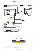
General operation time characteristic for the locked rotor element - 51LR
t-int-51LR.ai
I
I
LR
>>
def
t
LR
>
inv
t
LR
>>
def
I
LR
>
inv
t
I
MOT-ST
TRIP
XMR-D EQUIPMENT MANUAL
Ed. 2.9 - 02/2021


