


FUNCTION CHARACTERISTICS
87
—
Overflux - 24
Preface
The overfluxing protection is used as protection of the generator and connected transformer (eg au-
xiliary services transformer) against loss of insulation between the laminations of the magnetic circuit
leading to overheating produced by the iron losses due to the induction increase (over-excitation).
The overfluxing condition may occur:
• With generators disconnected from the network during start-up or standing, due to automatic con-
trol of the voltage regulator which, at low frequency, forces excitation increasing the flux in order
to keep the voltage constant.
• For failure of the voltage regulator in automatic control or wrong operations on manual control.
• Following the over-voltage produced by the shedding of a significant load, whilst the voltage regu-
lator is not operating sufficiently quickly to reduce the overvoltage.
The device measures the relationship
U
/
f
, which is proportion to the magnetic flux, the calculation
is based on the ratio between the maximum voltage of the three phase-to-phase voltages and the
frequency.
To better adapt itself to the limit curve of the admissible induction of the generator and transformer,
the protective device makes use of an alarm (
U
/
f
)
AL
and two, independently adjustable and delayed
(
t
U/fAL
,
t
U/f
>,
t
U/f
>>), trip thresholds (
U
/
f
)> and (
U
/
f
)>>.
A start is issued when the
U
/
f
=
U
MAX
/f ratio goes up the adjustable threshold; after expiry of the as-
sociated operate time a trip command is issued; if instead the ratio drops below the threshold, the
element is restored.
The alarm threshold (
U
/
f
)
AL
have a definite time characteristic.
The first trip threshold (
U
/
f
)> may be programmed with definite or inverse time characteristic by set-
ting the
U/f> Time characteristic
parameter (
DEFINITE, IEC type A, IEC type B, IEC type C
)
available inside the
Set \ Profile A (or B) \
Overexcitation - 24 \ (U/f)> Element \ Setpoints
menu.
The second threshold (
U
/
f
)>> have a definite time characteristic.
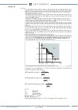
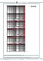
The operate time, corresponding to a
U
/
f
ratio of 1.5 times the threshold, can be determined
analytically using the formulas below:
where:
t:
operate time
U
/
f
:
input value
(
U
/
f
)>:
threshold setting
t
U/f
>:
operate time setting
Minimum ratio(
U
/
f
) : 1.1 (
U
/
f
)>
Minimum operate time: 0.1 s
Range where the equation is valid: 1.1 ≤ (
U
/
f
)> ≤ 5, the upper limit for measuring is 10 U
n
/f
n
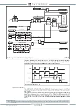
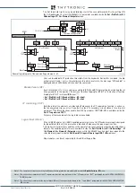
t-int-F24.ai
(
U/f
)
AL
U/f
(
U/f
)>
t
U/f
>
t
U/fAL
t
t
U/f
>>
(
U/f
)>>
1.1(
U/f
)>
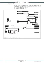
General operation time characteristic for the overflux elements - 24
TRIP
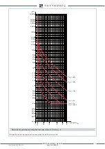
DEP A: type A IEC inverse time
t
U/f
>
0.02
0.0081
/
1
/
t
U f
U f
⋅
=
−
>
DEP B: type B IEC very inverse time
t
DEP C: type C IEC extremely inverse time
t
U/f
>
0.5
/
1
/
t
U f
U f
⋅
=
−
>
U/f
>
2
1.25
/
1
/
t
U f
U f
⋅
=
−
>
XMR-D EQUIPMENT MANUAL
Ed. 2.9 - 02/2021


