


FUNCTION CHARACTERISTICS
243
—
Phase directional overcurrent - 67
Preface
The protection is available in the XMR-B, XMR-V, XMR-P and XMR-G versions.
Four operation thresholds, independently adjustable with adjustable delay .
Each overcurrent element can be enabled or disabled.
The first two may be programmed with definite or inverse time according the IEC and ANSI/IEEE
standard, as well as with rectifier, I
2
t or EM curve.
The third and fourth thresholds with independent time.
Several operating mode are provided:
• Module or projection operating mode.
• One phase or two phase operating logic.
• 74VT internal and/or external logic.
Moreover several predefined blocking criteria are implemented (threshold trip may be inhibited by
start of the other thresholds, logic selectivity with internal and/or external elements, etc.).
To increase reliability for three phase short circuits close the VTs, a voltage memory is provided; this
memory voltage is used for reference to detect fault direction when all phase-to-phase voltages are
lower than 2%
U
n
and remains valid for 1 s after voltage collapse.
Operation and settings
The first and second threshold (
I
PD
>,
I
PD
>>) may be programmed with definite or inverse time accor-
ding the following characteristic curves:
• Standard Inverse Time (IEC 255-3/BS142 type A or SIT):
t
= 0.14 ·
t
PD
>
inv
/ [(
I
PD
/
I
PD
>
inv
)
0.02
- 1]
• Very Inverse Time (IEC 255-3/BS142 type B or VIT):
t
= 13.5 ·
t
PD
>
inv
/ [(
I
PD
/
I
PD
>
inv
) - 1]
• Very Inverse Time (IEC 255-3/BS142 type B or LIT):
t
= 120 ·
t
PD
>
inv
/ [(
I
PD
/
I
PD
>
inv
) - 1]
• Extremely Inverse Time (IEC 255-3/BS142 type C or EIT):
t
= 80 ·
t
PD
>
inv
/ [(
I
PD
/
I
PD
>
inv
)
2
- 1]
• Moderately Inverse (ANSI/IEEE type MI):
t
=
t
PD
>
inv
· {0.01 / [(
I
PD
/
I
PD
>
inv
)
0.02
- 1] + 0.023}
• Very Inverse (ANSI/IEEE type VI):
t
=
t
PD
>
inv
· {3.922 / [(
I
PD
/
I
PD
>
inv
)
2
- 1] + 0.098}
• Extremely Inverse (ANSI/IEEE type EI):
t
=
t
PD
>
inv
· {5.64 / [(
I
PD
/
I
PD
>
inv
)
2
- 1] + 0.024}
• Rectifier (RI):
t
= 2351 ·
t
PD
>
inv
/ [(
I
PD
/
I
PD
>
inv
)
5.6
- 1]
• I-squared-t (
I
2
t = K):
t
= 16 ·
t
PD
>
inv
/ (
I
PD
/
I
PD
>
inv
)
2
• Electromechanical (EM):
t
=
t
PD
>
inv
· {0.28 / [-0236 · (
I
PD
/
I
PD
>
inv
)
-1
+ 0.339]}
Where:
t
:
operate time
I
PD
>
inv
:
first and second threshold setting (
I
PD>inv,
I
PD>>inv
)
t
PD
>
inv
:
first and second threshold operate time setting (
t
PD>inv,
t
PD>>inv
)
Third and fourth threshold (
I
PD>>>def,
I
PD>>>>def
) with definite time.
For all inverse time characteristics, following data applies:
• Asymptotic reference value (minimum pickup value): 1.1
I
PD
> or
I
PD
>>
• Minimum operate time: 0.1
s
• Range where the equation is valid:
1
1.1 ≤
I
PD
/
I
PD
>
inv
(or
I
PD
>>
inv
) ≤ 20
• If
I
PD
>
inv
(or
I
PD
>>
inv
) pickup ≥ 2.5
I
n
, the upper limit is 50
I
n
• For all definite time elements the upper limit for measuring is 50
I
n
.
Two different criteria may be selected:
• Phase current threshold overcoming
(module
)
Projection current threshold overcoming
(projection
) For both operating mode the phase-to-phase
voltage in quadrature with the current the polarizing voltage, is used as phase reference for phase
reference for the operating current (phase-to-phase voltage 90° lagging compared with current for
cos
φ
= 1).
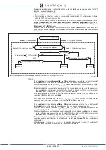
Note 1 When the input value is more than 20 times the set point , the operate time is limited to the value corresponding to 20 times the set point
I
PD
I
PD
>>
I
PD
>>>
I
PD
>>>>
t
PD
>
t
PD
>>
t
PD
>>>
t
PD
>>>>
I
PD
>
t
General operation time characteristic for phase directional overcurrent elements - 67
TRIP
NO TRIP
XMR-D EQUIPMENT MANUAL
Ed. 2.9 - 02/2021


