


244
FUNCTION CHARACTERISTICS
Therefore, for both operating mode, the following criteria applies:
• L1 phase:
a
1
phase displacement of the
I
L1
current phasor compared with the
U
23
, phasor, negative
for lagging current compared with voltage (
a
1
=
∠
U
23
-
∠
I
L1
).
• L2 phase:
a
2
phase displacement of the
I
L2
current phasor compared with the
U
31
, phasor, negative
for lagging current compared with voltage (
a
2
=
∠
U
31
-
∠
I
L2
).
• L3 phase:
a
3
phase displacement of the
I
L3
current phasor compared with the
U
12
, phasor, negative
for lagging current compared with voltage (
a
3
=
∠
U
12
-
∠
I
L3
).
The operating mode may be selected by setting the
Mode67
parameter, located inside the
Set \
Profile A (or B) \ Directional phase overcurrent-67 \
Common configuration
menu.
The settable operating mode is
I
(module) or
I*cos
(projection).
For each of the four thresholds (
I
PD>
,
I
PD>>
,
I
PD>>>
,
I
PD>>>>
), the characteristic angle (
q
>,
q
>>,
q
>>>,
q
>>>>) may be adjusted (setting range 0…359° common for the three phases).
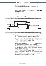
The characteristic angle setting (positive when counterclockwise compared the polarizing voltage)
specifies the angular displacement of the characteristic axis standing for the trip bisector of the
tripping zone (half plane 180° wide).
With a characteristic angle setting inside the 0°...90° or 270°...359° range the faults in the “LINE zone”
are detected, while with a characteristic angle setting inside the 91°...269 range the faults in the
“BUS zone” are detected.
All the named parameters can be set separately for the four thresholds and for definite or inverse
time settings menus.
char-F67-modulo.ai
Operating characteristics of the phase directional overcurrent elements - 67 with module operating mode
XMR
BUSBAR
I
L1
I
L2
I
L3
U
L1
U
L2
U
L3
VOLTAGE INPUTS
CURRENT INPUTS
LINE
I
L1,
I
L2,
I
L3
L1 phase
L2 phase
L3 phase
I
L 3
U
L 2
U
L 3
U
L1
α3
U
12
U
12
I
L 2
U
31
U
31
U
L 2
U
L 3
U
L1
α2
U
2 3
U
2 3
I
L1
Threshold:
(
I
PD
>,
I
PD
>>,
I
PD
>>>,
I
PD
>>>>)
Threshold:
(
I
PD
>,
I
PD
>>,
I
PD
>>>,
I
PD
>>>>)
Threshold:
(
I
PD
>,
I
PD
>>,
I
PD
>>>,
I
PD
>>>>)
Characteristic angle:
(ThetaP>, ThetaP>>,
ThetaP>>>, ThetaP>>>>)
Characteristic angle:
(ThetaP>, ThetaP>>,
ThetaP>>>, ThetaP>>>>)
Characteristic angle:
(ThetaP>, ThetaP>>,
ThetaP>>>, ThetaP>>>>)
α1
U
L 2
U
L 3
U
L1
Characteristic axis
Characteristic axis
Characteristic axis
Trip sector
Toward line
Trip sector
Toward line
Trip sector
Toward line
No trip sector
Toward busbar
No trip sector
Toward busbar
No trip sector
Toward busbar
I
≥
I
PD threshold
I
PD threshold
I
I∙cos
Mode67
A3-A5-A7 terminals
B1-B3-B5 terminals
XMR-D EQUIPMENT MANUAL
Ed. 2.9 - 02/2021


