


286
FUNCTION CHARACTERISTICS
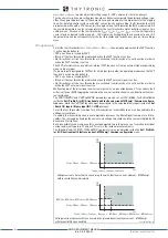
that is the -
β
E
≤ (
Θ
E
-
Φ
E
) ≤ +
β
E
condition is fulfilled.
[1]
If the operation mode is switched to “not directional” (by the 74VT function), the start of any 67N
threshold becomes active when the following is complied:
- The residual current (
I
E
) fundamental component overcomes the threshold (
I
EDC>
,
I
EDC>>
,
I
EDC>>>
,
I
EDC>>>>
)
For both the operating mode (module or projection), when the start signal goes ON a concerning
counter starts; after expiry of the associated operate time (
t
EDC>
,
t
EDC>>
,
t
EDC>>>
,
t
EDC>>>>
) a trip com-
mand is issued, if instead the above conditions don’t remain valid, the element it is restored.
All the parameters are located inside the menus concerning the four elements, separately for defini-
te and inverse time characteristics.
Example: the operate time concerning the first threshold with definite time characteristic (
IEDC>-
def
) is available inside the
Set \ Profile A (or B) \ Directional earth fault overcurrent-67N(Comp) \
IEDC> Element
\ Definite time
menu.
All directional earth fault overcurrent elements can be enabled or disabled by setting
ON
or
OFF
the
IEDC> Enable
,
IEDC>> Enable,
,
IEDC>>> Enable
e/o
IEDC>>>> Enable
parameters in-
side the
Set \ Profile A (or B)\Directional earth fault overcurrent-67N(Comp) \
IEDC> Element
(
IEDC>>
Element
,
IEDC>>> Element
,
IEDC>>> Element) \ Setpoints
menus.
The first and second overcurrent element can be programmed with definite or inverse time characte-
ristic by setting the
IEDC>Curve
and/or
IEDC>>Curve
(
DEFINITE, IEC/BS A, IEC/BS B, IEC/
BS C, ANSI/IEE MI, ANSI/IEE VI, ANSI/IEE EI, EM
) available inside the
Set \ Profile A (or B) \
Directional earth fault overcurrent-67N(Comp) \
IEDC> Element
(
IEDC>> Element) \ Setpoints
menus.
The trip of IEDC> element may be inhibited by the start of the second, third and/or fourth element
(
I
EDC>>
,
I
EDC>>>
,
I
EDC>>>>
) by setting
ON
the Disable IEDC> by start IEDC>>, Disable IEDC> by start
IEDC>>>, Disable IEDC> by start IEDC>>>> (
IEDC>disbyIEDC>>, IEDC>disbyIEDC>>>, IE-
DC>disbyIEDC>>>>
) parameters available inside the
Set \ Profile A (or B) \ Directional earth
fault overcurrent-67N(Comp) \ IEDC>> Element
(
IEDC>>> Element, IEDC>>>> Element) \ Setpoints
menus.
Similarly the trip of the:
• IEDC>> element may be inhibited by start of the third and/or fourth element (
IEDC
>>> and/or
IEDC
>>>>) by setting
ON
the Disable IEDC>> by start IEDC>>>, start IEDC>>>> (
IEDC>>di-
sbyIEDC>>>, IEDC>>disbyIEDC>>>>
) parameter available inside the
Set \ Profile A (or B)
\ Directional earth fault overcurrent-67N(Comp) \ IEDC>>> Element (IEDC>>>> Element) \ Setpoints
menus.
• IEDC>>> element may be inhibited by start of the fourth element (
IEDC
>>>>) by setting
ON
the Di-
sable IEDC>>> by start IEDC>>>> (
IEDC>>>disbyIEDC>>>>
) parameter available inside the
Set \ Profile A (or B) \ Directional earth fault overcurrent-67N(Comp) \ IEDC>>>> Element \ Setpoints
menu.
All the named parameters can be set separately for
Profile A
and
Profile B
.
An adjustable reset time delay is provided for every threshold
(
t
EDC>RES
,
t
EDC>>RES
,
t
EDC>>>RES
,
t
EDC>>>>RES
).
Breaker failure (BF)
Each thresholds (IEDC>, IEDC>>, IEDC>>>, IEDC>>>>) can be associated to BF (H) and BF (L) protec-
tion by activating the relative parameter in the matrices “Selection of function tripping for BF (H)” or
“Selection of function tripping for BF (L)” in relevant
BF
menus
[2]
:
• Set \ Profile A (or B) \ Breaker failure - BF side H
• Set \ Profile A (or B) \ Breaker failure - BF side L
Cold load pickup (CLP)
The selection of current measurement type IECH/IECL defines the CB that is monitored for 67N(Comp)
CLP function starting. If IECH is selected, CB side H is monitored. If IECL is selected, CB side L is mo-
nitored.
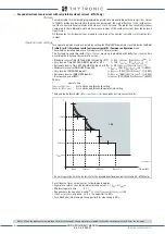
Note 1 For each threshold the projection of the residual current phasor on the characteristic axis is:
(
I
ECH
or
I
ECL
)
cos(
Θ
E
>-
Φ
E
), I
(
I
ECH
or
I
ECL
)
cos(
Θ
E
>>-
Φ
E
),
(
I
ECH
or
I
ECL
)
cos(
Θ
E
>>>-
Φ
E
),
(
I
ECH
or
I
ECL
)
cos(
Θ
E
>>>>-
Φ
E
) when “direct” residual voltage is selected (U
E
), or
I
ECH
or
I
ECL
)
cos(
Θ
E
>-
Φ
EC
),
(
I
ECH
or
I
ECL
)
cos(
Θ
E
>>-
Φ
EC
),
(
I
ECH
or
I
ECL
)
cos(
Θ
E
>>>-
Φ
EC
),
(
I
ECH
or
I
ECL
)
cos(
Θ
E
>>>>-
Φ
EC
) when “calculated”
residual voltage is selected (U
EC
).
The
Θ
E
,
β
E
and
Φ
EC
symbols are not used inside the Thyvisor and MMI menus.
Note 2 The common settings concerning the Breaker failure protection are adjustable inside the
Breaker Failure - BF
menu.
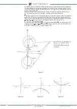
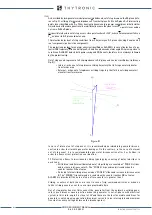
Timers-F67NC.ai
IEDC> Start
IEDC> Trip
t
EDC>
t
EDC>
RESET
INPUT
t
EDC>RES
t
EDC>RES
t
EDC>RES
t
67N(Comp) element timers - 67N(Comp) (first element)
XMR-D EQUIPMENT MANUAL
Ed. 2.9 - 02/2021


