


298
FUNCTION CHARACTERISTICS
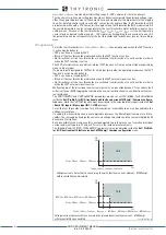
Measurement criterion
Out of step phenomenon is typically symmetrical, therefore it can be detected by means of direct
sequence impedance measurement.. The impedance value for 78 protection is therefore obtained
by the ratio between phasors of direct cyclical sense U
1
voltage and direct cyclical sense I
1
current:
where Z and
φ
are respectively the module and the argument of impedance Z, while R and X represent
respectively the resistive and reactive component.
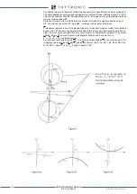
Adjustment
Electrical system Z
G
, Z
T
and Z
N
impedances adjustments introduced in dual generator model are pa-
rameterized in XMR protection relay introducing a further model simplification through adjustable
parameters Z
A
, Z
B
, Z
C
e
ꞵ
.
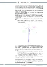
Z
A
represents the sum of external network (Z
N
) and step-up transformer (Z
T
) impedance modules re-
lated to Z measuring point.
Z
B
represents generator reactance module.
Z
C
represents the module of discrimination impedance between internal and external out of step ge-
nerator/transformer group (ZONE B internal sliding ONLY, ZONE A for ALL sliding).
ꞵ
represents the angle formed by abscissa axis with straight line where system impedances Z
A
, Z
B
e
Z
C
lie.
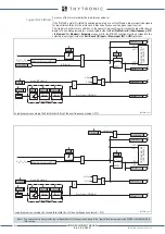
Note that the origin of R-X plane correspond to measurement point. Adopted system impedance mo-
del (Fig. F) represents a further approximation of the dual generator model shown in Figure E.
Z
A
, Z
B
, Z
C
and
ꞵ
parameters calculation must be carried out in consideration of electricity
grid parameters and its possible operating scenarios, downstream of appropriate studies
of stability / electromagnetic transients. Below some guidelines in order to define men-
tioned parameters preset:
• Z
A
represents electrical system and step-up transformer impedance ( Z
A
= Z
T
+ Z
N
),
seen from measurement point; it is programmed in relative value referred to Z
nf
• Z
B
represents synchronous generator impedance. In order to define correctly this
parameter it is necessary consider that during out of step phenomena the generator
impedance changes over time according to synchronous machine dynamics.
XMR-D EQUIPMENT MANUAL
Ed. 2.9 - 02/2021


