


295
FUNCTION CHARACTERISTICS
The angle
δ
represents the phase shift between generator voltage EG and the mains voltage EN.
This angle depends on network load and operating conditions. During stable operation,
δ
is relati-
vely constant and less than 90°. During hunting events, this angle varies considerably, but usually
remains at values below 90°.
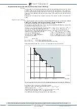
During out of step (system stability which cannot be restored) this angle exceeds the value of
90 °, varying from the value of 0 ° up to 360 °, making a circular path on R-X plane.
Z impedance representation in R-X plane during out of step event is represented by locus defined
by equation (*). The measuring point is identified with R-X plane origin. Assuming the ratio M con-
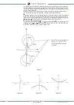
stant, an out of step event identifies the circumferences as represented in Figure C. The center
and the radius of the circumferences are defined by M value and the center lies on
Z
TOT
= Z
G
+ Z
T
+ Z
N
straight projection.
Pay attention that
δ
angle at point Z
P
of circumference identified by Z is the vertex angle of the
triangle geometrically identified by Z
P
and by Z
P
extremes (Fig. D1 for M = 1, Fig. D2 for M> 1, Fig.
D3 for M <1): if point Z
P
is on Z
TOT
δ
angle is equal to 180°.
XMR-D EQUIPMENT MANUAL
Ed. 2.9 - 02/2021


