


192
FUNCTION CHARACTERISTICS
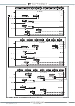
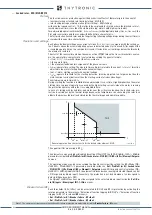
Residual overcurrent (50N.1/51N.1) - Second element logic diagram (IE1>>) (Sheet 1 of 2)
Fun_50N-51NS2.ai
t
E1>>RES
T
0
RESET
t
E1>>
0
T
≥
1
t
E1>>def
t
E1>>RES
Start IE1>>
Trip IE1>
>
CB-State
Start
I
2ndh>
IE1
>
> inhibition
Block1, Block2, Block4
&
IE1>
>
TR-K
IE1>
>
TR-L
IE1>
>
ST-L
IE1>
>
ST-K
T
0
t
ECLP>>
&
2nd harmonic restraint enable (ON
≡
Enable)
IE1>>2ndh-REST
IE1CLP>>Mode
t
E1CLP>>
TR
IP
PI
NG M
AT
RI
X
(LE
D+R
EL
AY
S)
A
B
C
Output
t
ECLP>>
IE1
>>
Enable
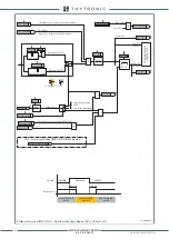
IE1>> overcurrent element (50N.1/51N.1) Block diagram
t
E1CLP>>
CB State
CB OPEN
CB CLOSED
CB OPEN
Output t
E1CLP
>
>
t
0.1 s
HIGH THRESHOLD/
BLOCK
LOW THRESHOLD/
UNBLOCK
HIGH THRESHOLD/
BLOCK
A = ON - Change setting
B = OFF
C = ON - Element blocking
&
(ON
≡
Inhibit)
Start IE1>>
Start IE1>>
IE1> inhibition
IE1> disbylE>>
≥
1
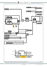
CLP IE1>>
ON
≡
Inhibit
(from IE1>>> residual overcurrent element)
ON
≡
Enable IE1>> residual overcurrent element
I
E1>>def
A =“1”
A =“0 or OFF”
I
E1
(Pickup within CLP)
(Pickup outside CLP)
I
E1CLP>>def
I
E1
≥
I
E1CLP
>>def
&
State
I
E1
≥
I
E1
>>
def
XMR-D EQUIPMENT MANUAL
Ed. 2.9 - 02/2021


