


INSTALLATION
367
Hence, the assembly indicated in the drawing of fig.2b, in which phase L3 causes local magnetic
saturation whereby the vectorial sum of the three currents would be non-null, should be avoided.
The same considerations also apply when the sensor is positioned near bends in the cabling.
It is recommended that the transformer be placed away from bends in the conductors (fig 2c).
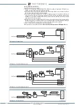
Binary inputs
The input circuits are voltage-free; activation requires the application of a power source, preferably
the same auxiliary voltage present in the switchboard.
The inputs are dimensioned for a wide range of operation and does not require any hw and / or sw
programming.
For all connections longer than 5m or in environments particularly subject to disturbances due to
power transmission, the use of shielded cables is
strictly
recommended, with the shield connected
to earth on only one end..
Fig. 2a
Fig. 2b
Fig. 2c
L1
L3
L2
L1
L3
L2
Toroide.ai
Installation Current Balanced Transformer
Binary Inputs
+
U
AUX
-
U
AUX
A
B
IN2G
IN3H
1
2
BINARY INPUTS
F1
IN1-1
IN1-2
F2
F3
F4
IN1-3
IN1-4
F5
F6
IN1-5
IN1-6
F7
F8
F9
F10
IN1-7
H1
IN3-1
IN3-2
H2
H3
H4
IN3-3
IN3-4
H5
H6
IN3-5
IN3-6
H7
H8
H9
H10
IN3-7
IN1F
BINARY INPUTS
G1
IN2-1
IN2-2
G2
G3
G4
IN2-3
IN2-4
G5
G6
IN2-5
IN2-6
G7
G8
G9
G10
IN2-7
BINARY INPUTS
The inputs are immune to transitory interferences, however the following recommendation must be
considered in high disturbed environments:
• Position input wiring away from high energy sources
• Set a debounce timer (tON and/or tOFF) to alloy the transient to decay
• Use shielded cables with ground connection on only one end (preferably at the relay side)
WARNING
XMR-D EQUIPMENT MANUAL
Ed. 2.9 - 02/2021


