UART/IrDA/CIR
Controller
UART_IRTX
UART_IRRX
UART_SD
IrDA transceiver
RXD(IrDA)
TXD
SD/MODE
UART_RCTX
RC(CIR)
Preliminary
www.ti.com
Architecture
19.2.4 IrDA Mode
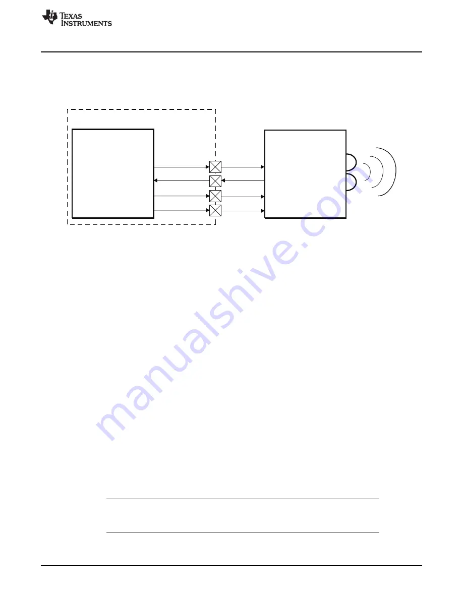
This section describes the IrDA connection with an external device.
shows how UART3 can
be connected to an external infrared transceiver in the IrDA mode.
Figure 19-3. UART IrDA to External IR Device
The module performs serial-to-parallel conversion on received data characters and parallel-to-serial
conversion on transmitted data characters by the processor. The complete status of each channel of
the module and each received character/frame can be read at any time during functional operation via
the line status register (LSR).
The module can be placed in an alternate mode (FIFO mode) relieving the processor of excessive
software overhead by buffering received/transmitted characters. Both the receiver and transmitter
FIFOs can store up to 64 bytes of data (plus three additional bits of error status per byte for the receiver
FIFO) and have selectable trigger levels. Both interrupts and DMA are available to control the data-flow
between the LH and the module.
19.2.4.1 SIR Mode
In slow infrared (SIR) mode, data transfer takes place between the LH and peripheral devices at
speeds of up to 115200 bauds speed. A SIR transmit frame starts with start flags (either a single C0h,
multiple C0h, or a single C0h preceded by a number of FFh flags), followed by frame data, CRC-16 and
ends with a stop flag (C1h). The bit format for a single word uses a single start bit, eight data bits and
one stop bit and is unaffected by the use and settings of the LCR register.
Note that BLR[6] is used to select whether C0h or FFh start patterns is to be used, when multiple start
flags are required. The SIR transmit state machine attaches start flags, CRC-16 and stop flags. It
checks the outgoing data to establish if data transparency is required. SIR transparency is carried out if
the outgoing data, between the start and stop flags, contains C0h, C1h, or 7Dh. If one of these is about
to be transmitted, then the SIR state machine sends an escape character (7Dh) first, then inverts the
fifth bit of the real data to be sent, and sends this data immediately after the 7Dh character.
The SIR receive state machine recovers the receive clock, removes the start flags, removes any
transparency from the incoming data and determines frame boundary with reception of the stop flag. It
also checks for errors such as: frame abort (0x7D character followed immediately by a C1h stop flag,
without transparency), CRC error and frame-length error. At the end of a frame reception, the LH reads
the line status register (LSR) to find out possible errors of the received frame.
NOTE:
Data can be transferred both ways by the module, but when the device is transmitting,
the IR RX circuitry is automatically disabled by hardware. See the UART3.ACREG[5]
DIS_IR_RX bit description. This applies to all three modes: SIR, MIR, and FIR.
1687
SPRUGX9 – 15 April 2011
UART/IrDA/CIR Module
© 2011, Texas Instruments Incorporated
Содержание TMS320C6A816 Series
Страница 2: ...Preliminary 2 SPRUGX9 15 April 2011 Submit Documentation Feedback 2011 Texas Instruments Incorporated...
Страница 92: ...92 Read This First SPRUGX9 15 April 2011 Submit Documentation Feedback 2011 Texas Instruments Incorporated...
Страница 1122: ...1122 Multichannel Audio Serial Port McASP SPRUGX9 15 April 2011 Submit Documentation Feedback 2011 Texas Instruments Incorporated...
Страница 1562: ...1562 Real Time Clock RTC SPRUGX9 15 April 2011 Submit Documentation Feedback 2011 Texas Instruments Incorporated...
Страница 1658: ...1658 Timers SPRUGX9 15 April 2011 Submit Documentation Feedback 2011 Texas Instruments Incorporated...
Страница 1750: ...1750 UART IrDA CIR Module SPRUGX9 15 April 2011 Submit Documentation Feedback 2011 Texas Instruments Incorporated...
Страница 1984: ...1984 Universal Serial Bus USB SPRUGX9 15 April 2011 Submit Documentation Feedback 2011 Texas Instruments Incorporated...


