


CPU Module (CMOD) Overview
.
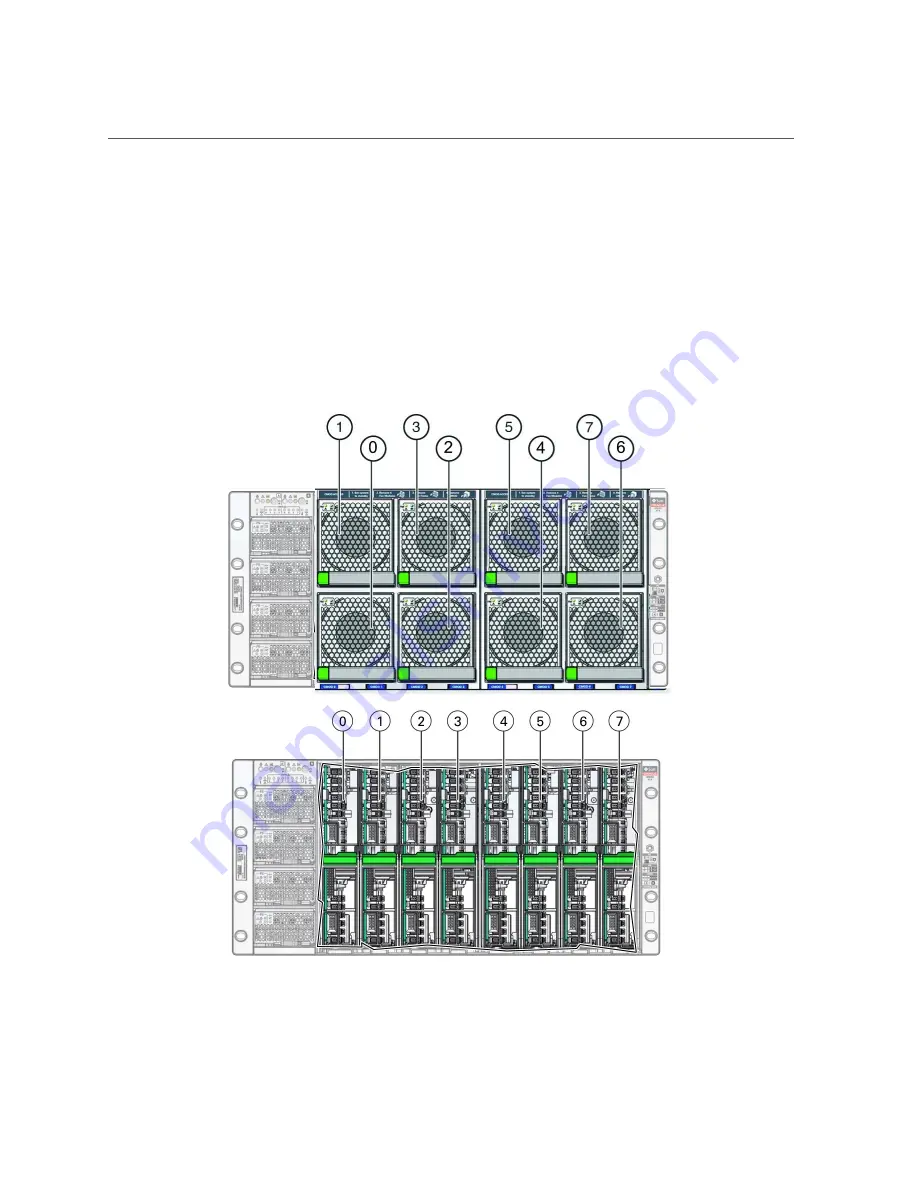
CMOD and Fan Module Power
Fan modules (FMs) recieve power from CMODs. However, only CMODs in even-numbered
slots supply power to fan modules. The following table shows which CMOD slots provide FM
power. Four fan modules per SMOD are front panel accessible.
About the Oracle Server X7-8
33
Содержание X7-8
Страница 1: ...Oracle Server X7 8 Service Manual Part No E71936 01 October 2017 ...
Страница 2: ......
Страница 13: ...Contents Index 303 13 ...
Страница 14: ...14 Oracle Server X7 8 Service Manual October 2017 ...
Страница 16: ...16 Oracle Server X7 8 Service Manual October 2017 ...
Страница 46: ...46 Oracle Server X7 8 Service Manual October 2017 ...
Страница 268: ...268 Oracle Server X7 8 Service Manual October 2017 ...
Страница 294: ...294 Oracle Server X7 8 Service Manual October 2017 ...


