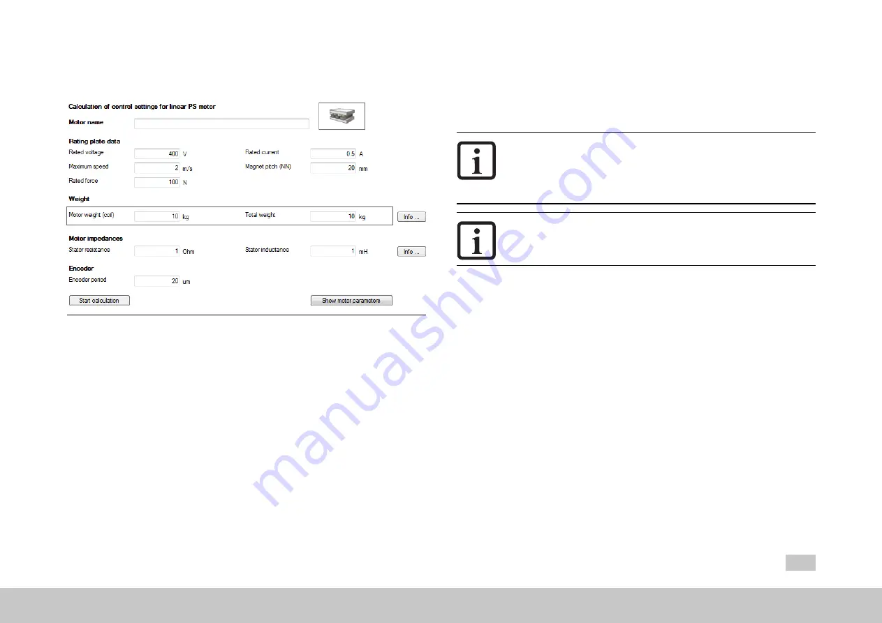
5.3 Linear synchronous motor
Image 5.4: “Linear synchronous motor settings” screen
There are two methods of creating a motor data set for the linear synchronous motor.
l
Variant 1: Motor calculation
l
Variant 2: Motor identification (see Section "Motor identification" on page 45)
Variant 1: Motor calculation
l
Enter the motor data
The motor data relevant to the calculation must be entered from the data
sheet.
l
Click on “Start calculation”.
l
If the moment of inertia of the motor
P 461 - Mot_J
is not known, a value
roughly corresponding to the motor's moment of inertia must be applied.
MOOG
ID No.: CB40859-001 Date: 11/2020
MSD Servo Drive - Device Help
36
5 Motor
l
The calculation process can be monitored in the Moog D
RIVE
A
DMINISTRATOR
5 via the menu, View, Messages.
l
Calculation of operating point: Flux
P 462 - MOT_FLUXNom
l
Calculation of: current, speed and position control parameters
NOTE
l
P 490 - MOT_ISLinRot
= LIN(1): The parameter automatically sets
the number of pole pairs for the motor to
P 463 - Mot_PolePairs
=
1. As a result, a North to North pole pitch corresponds to one
virtual revolution
(P 492 - Mot_MagnetPitch).
NOTE
l
All existing motor parameters are overwritten.
Calculated values
l
Translation of the linear nominal quantities into virtual rotary nominal
quantities
l
Default values for auto commutation
l
Encoder lines per virtual revolution
l
Flux settings (including for torque constant)
l
Control settings for PI current controller: the current controller is dimensioned
based on the actual switching frequency set.
l
PI speed controller and position controller gain: A moderately rigid
mechanism and moment of inertia matching from load to motor with a ratio of
1:1 is assumed here.
l
The default value for speed tracking error monitoring corresponds to 50% of
the nominal speed.
l
V/F characteristic


