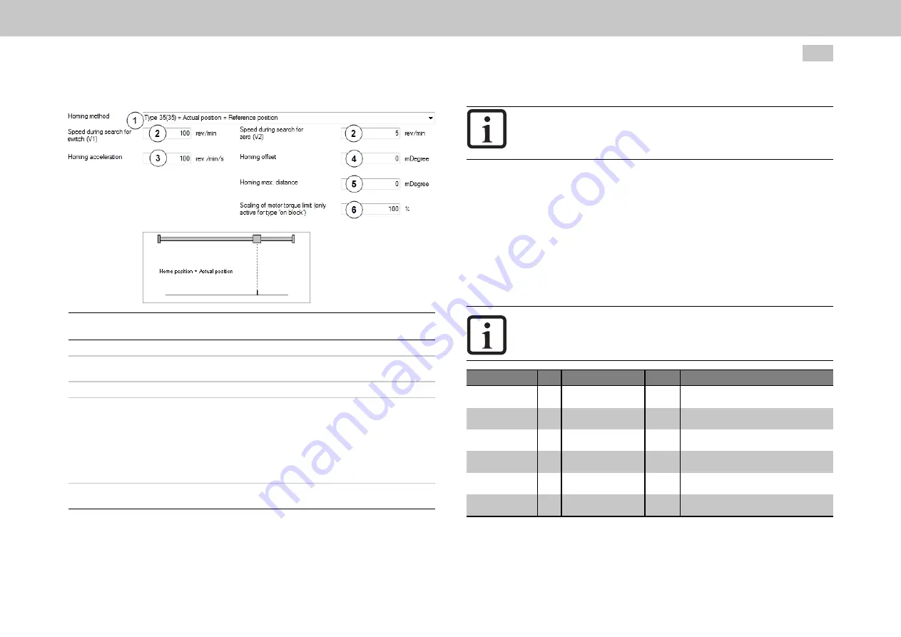
Image 8.38: Selection of homing method
①
Selection of homing methods (-12) to (35)
②
Speed V1: Speed during cam search
Speed V2: Speed during zero point search
③
Acceleration for V1 and V2
④
The reference point usually has an actual position value defined on the axis side
referred to the axis zero.
Ideally, the position value of the drive-side datum point and of the reference
point are identical. As the position of the datum point is decisively influenced by
the encoder mounting, however, the datum and reference points differ.
To establish a positional reference to the real axis zero, the desired axis-related
actual position value of the reference point should be set via the zero offset.
⑤
Limitation of positioning range for homing. On exiting the positioning range, the
axis is stopped with the error message "Overrun".
Legend for “‘Homing method’ screen” figure
MOOG
ID No.: CB40859-001 Date: 11/2020
MSD Servo Drive - Device Help
250
8 Motion profile
NOTE
l
The reference mark signal can be optionally linked to one of the
ISD05 and ISD06 fast digital inputs.
8.5.1.1 Homing to a limit switch:
The digital input must be set to the available selection parameter LCW(5) for a
positive limit switch or to LCCW(6) for a negative limit switch.
8.5.1.2 Homing to a cam
Set digital input to HOMSW(10) (P 106 - MPRO_INPUT_FS_ISD06 to P 107-
MPRO_INPUT_FS_ISD07).
NOTE
l
The homing methods (-1) to (-12) are manufacturer-specific.
Homing methods (0) to (35) are defined according to CiA 402.
ID
Index Name
Unit
Description
169
0
MPRO_REF_
HOMING_MaxDistance
mDegree Homing: Maximum travel (homing to block:
block detection)
170
0
MPRO_REF_
HOMING_Ctrl
Homing method Controlword
171
0
MPRO_REF_
HOMING_BackupPos
mDegree Homing: backup position
225
0
MPRO_REF_
HOMING_TMaxScale
%
Scaling of motor torque limit during homing
2234
0
MPRO_402_
HomeOffset
mDegree 607CH DS402 home offset
2261
0
MPRO_402_
HomingMethod
6098H DS402 homing method
Table 8.20: “Homing” parameters


