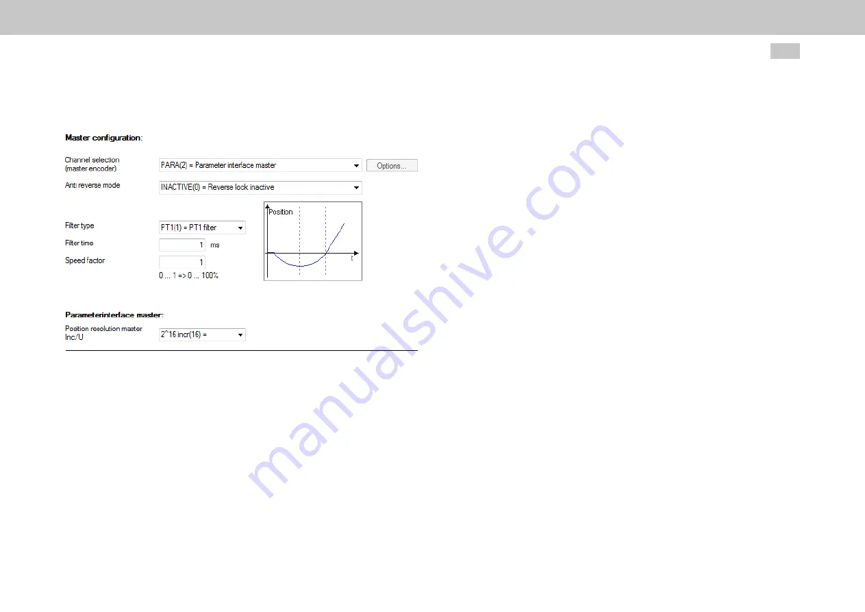
8.11.4 Master configuration
Image 8.72: “Master configuration” screen
Channel selection (master encoder)
P 1319[0] - MPRO_ECAM_CamMaster_AxisType is used to define the master
encoder.
l
NO AXIS (0) = No axis
l
VIRTUAL MASTER (1) = Virtual master
If you select this function, you will be able to configure additional settings by
clicking on the enabled “Options...” button (see Section "Virtual Master" on
page 286).
l
PARA (2) = Master parameter interface
If you select this function because a higher-level controller is being used as
MOOG
ID No.: CB40859-001 Date: 11/2020
MSD Servo Drive - Device Help
280
8 Motion profile
the master encoder, you will need to set the resolution relative to a single
motor revolution in
P 250 - MPRO_ECAM_PARAMaster_Amplitude
(see
below).
l
ENC CH1 (3) = Encoder channel 1 X7 (Sin/Cos)
l
ENC CH2 (4) = Encoder channel 2 X6 (Resolver)
l
ENC CH3 (5) = Encoder channel 3 X8 (optional)
This function is only available if an external interface X8 (option module) is
present.
l
TP0 (6) = Pulse counter on probe channel 0 (TP0)
l
TP1 (7) = Pulse counter on probe channel 1 (TP1)
l
ENC_CH4 (8) = Encoder channel 4 (p. e. fieldbus)
l
TWIN_POS (9) = TWIN remote reference position
(P-2607)


