


308
Routers & Kaleido-X
12
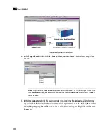
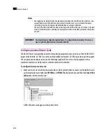
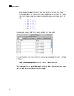
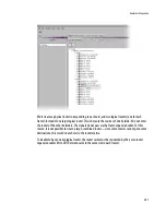
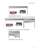
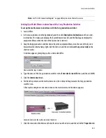
The cabling connections must then be described in XEdit.
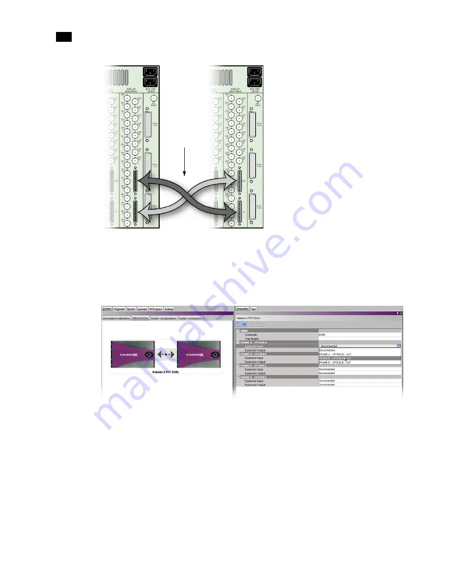
3. Click the
Interconnects
tab, then click the expansion frame icon. Under the
Properties
tab, notice
that there are four entries (two per frame) for the router cards (OPTION A and B) with rows labeled
Expansion Input
and
Expansion Output
. Normally, you connect the router cards in matching slots
(e.g. FRAME A – OPTION A to FRAME B – OPTION A):
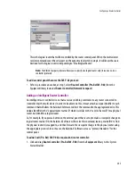
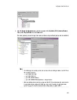
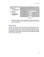
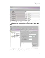
4. For
FRAME A – OPTION A
, click in the white column beside
Expansion Input
, and choose a
corresponding output option from the list. A progress window for the router configuration appears
briefly. Note that the corresponding (inverse) settings appear beside the card you connected to.
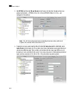
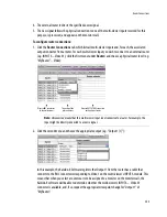
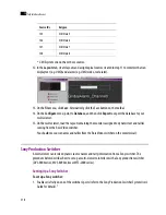
5. Click in the white column beside
Expansion Output
, and choose a corresponding input option from
the list.
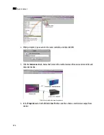
6. Repeat for
FRAME A – OPTION B
.
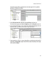
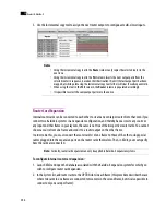
7.
OPTION A
and
B
for
FRAME B
are completed automatically:
Router Expansion
Cables
Содержание Kaleido-X
Страница 1: ...Kaleido X User s Manual Part Number M770 2800 111 1 June 2011 ...
Страница 8: ...viii toc ...
Страница 33: ...Loading a Layout 25 Kaleido X16 ...
Страница 34: ...26 Getting Started 2 Kaleido X 4RU ...
Страница 152: ...144 Creating Logical Sources 7 ...
Страница 178: ...170 Setting Up Rooms 8 ...
Страница 244: ...236 Creating Layouts 9 ...
Страница 253: ...Detailed Directions 245 3 Under Properties General type a Friendly name for the Action ...
Страница 256: ...248 Creating Actions 10 ...
Страница 272: ...264 Managing Kaleido RCP2 Users 11 ...
Страница 348: ...340 Tally Interface Devices 13 ...
Страница 350: ......
Страница 352: ...344 Using the Serial to TCP IP Dispatcher 15 ...
Страница 406: ...398 Index ...