


288
Routers & Kaleido-X
12
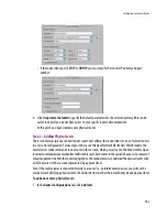
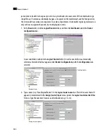
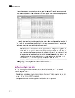
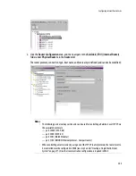
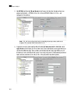
The new logical level appears in the
Levels
list, and also under the new sub-folder that represents the
logical router in the Routers list.
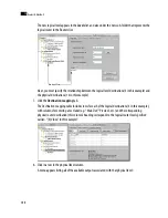
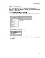
Next, you must specify the relationship between the logical level destinations (4 in this example) and
the physical destinations (16 in this example).
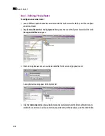
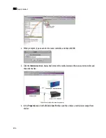
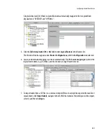
7. Click the
Destination mapping
tab.
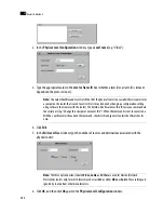
The Destination mapping table includes rows for each of the logical destinations (4 in this example),
with columns for entering a text label (e.g. “Main Out”, “Preview”, etc.) and the corresponding
physical router destination (this column’s heading corresponds to the logical router level specified
earlier–“[0] Video” in this example):
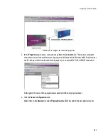
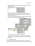
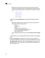
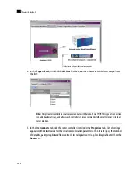
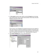
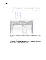
8. Click in a row in the physical level column.
A menu appears listing all of the available outputs associated with that physical level:
New logical level
Содержание Kaleido-X
Страница 1: ...Kaleido X User s Manual Part Number M770 2800 111 1 June 2011 ...
Страница 8: ...viii toc ...
Страница 33: ...Loading a Layout 25 Kaleido X16 ...
Страница 34: ...26 Getting Started 2 Kaleido X 4RU ...
Страница 152: ...144 Creating Logical Sources 7 ...
Страница 178: ...170 Setting Up Rooms 8 ...
Страница 244: ...236 Creating Layouts 9 ...
Страница 253: ...Detailed Directions 245 3 Under Properties General type a Friendly name for the Action ...
Страница 256: ...248 Creating Actions 10 ...
Страница 272: ...264 Managing Kaleido RCP2 Users 11 ...
Страница 348: ...340 Tally Interface Devices 13 ...
Страница 350: ......
Страница 352: ...344 Using the Serial to TCP IP Dispatcher 15 ...
Страница 406: ...398 Index ...