3-8
IM 701830-01E
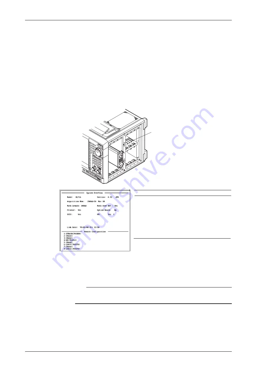
Installation procedure
1.
Make sure the POWER switch is OFF.
2.
Check the channel number indicated above the slots for installing the input modules on the
right side of the instrument. Then, install the module along the guide.
Holding the handles on the top and bottom of the input module, press hard until it clicks in
place.
If there is a cover plate on the slot in which to install the module, remove the cover plate,
first.
3.
Make sure to screw the two locations, top and bottom, of the input module firmly into place.
4.
Turn ON the power switch.
5.
Check to see that the correct input module name is displayed at the corresponding channel
number in the overview screen. If the display is not correct, remove the module according to
the steps in “Removal” shown below, and reinstall the module according to steps 1 to 3
shown above. For details on the overview screen, refer to Section 14.4 “Checking the
System Condition (Overview).”
Guide
Input module
High-Speed Isolation Module(701855)
High-Speed Module(701856)
High-Resolution, High-Voltage,
Isolation Module(701852)
High-Resolution, High-Voltage Module(701853)
Temperature Module(701860)
Logic Input Module(701870)
Strain Module(701880)
Abbreviation
HS_ISOL
HS
HR_HV
HR
TEMP
LOGIC
STRAIN
Removal
1.
Make sure the POWER switch is OFF.
2.
Loosen the screws holding the input module in place.
3.
Holding the handles on the top and bottom of the input module, pull out the module.
Note
High-Resolution, High-Voltage, Isolation/High-Resolution, Isolation/Temperature/Logic Input Modules
are only operate in products with software Version 2.00 or later.
For details, please contact the dealer from which you purchased them.
3.5 Installing the Input Module


