6-15
6
IM 701830-01E
Triggering
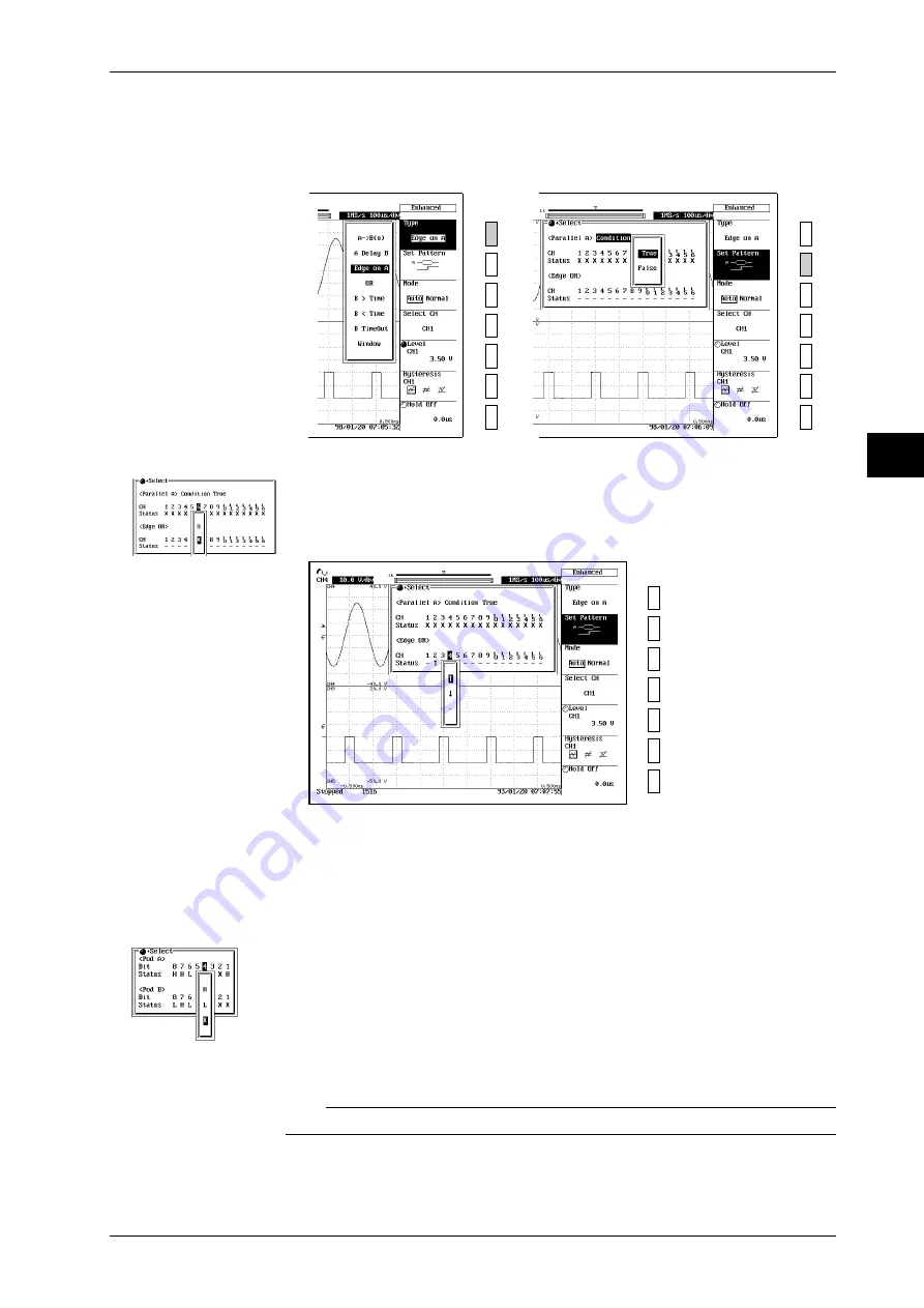
Setting condition A to true/false
4.
Press the “
Set Pattern
” soft key to display the Edge on A trigger setting menu.
5.
Turn the jog shuttle to move the cursor to the <Parallel A> “
Condition
.”
6.
Press the
SELECT
key to display the <Parallel A> “
Condition
” menu.
7.
Press the
SELECT
key again to select “
True
” or “
False
.”
→
Setting the channel status for condition A
8.
Turn the jog shuttle to move the cursor to “
CH1
” under <Parallel A>.
9.
Press the
SELECT
key to display the <Parallel A> CH1 menu.
10.
Press the same
SELECT
key the appropriate number of times to select from “
H
,” “
L
” and
“
X
” (“
O
” and“
X
” for logic input).
11.
Repeat the above steps to set the channel status for CH2 to CH16.
Setting edge OR
12.
Turn the jog shuttle to move the cursor to “
CH1
” under <Edge OR>.
13.
Press the
SELECT
key to display the CH1 menu.
14.
Press the
SELECT
key again to select “
↑
”, “
↓
” or “
–
.”
Setting the conditions of POD A and B (when using the logic input channel only)
15.
Press the “
Bit Pattern
” soft key. (This key is not displayed unless logic input channel is
selected with “
Select CH
.”)
16.
With the jog shuttle, move the cursor to the bit to which you wish to set the condition.
17.
Press the
SELECT
key to select “
H
,” “
L
,” or “
X
.”
Other settings
18.
You must also set the following parameters: trigger mode, trigger level, trigger hysteresis,
and holdoff time. For information about how to set these parameters, refer to Sections 6.1 to
6.7.
Note
Status settings for condition A apply in common to all trigger types.
6.11 Setting the Edge on A Trigger (ENHANCED)
Setting the status of
each bit on the logic
input channel
When the channel is
a Logic Input Module


