


Operation
3-30 Operation
Thermo Fisher Scientific
REC 4132 Rev
E
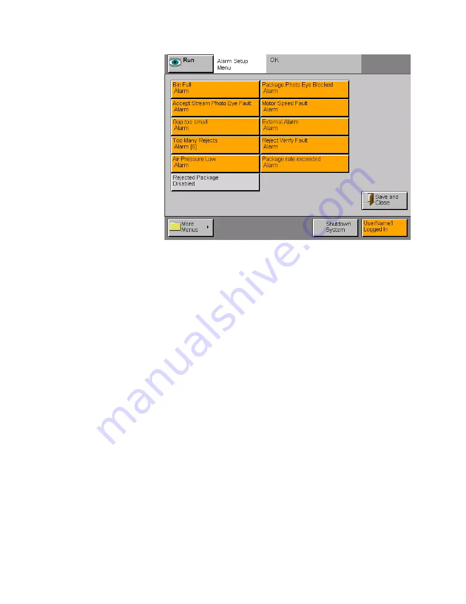
Alarm Setup Default
Figure 3–28.
User Configurable Alarms
•
Bin Full
– activated when the reject bin is full (requires photo eye)
•
Accept Stream Photo Eye Fault
– indicates a fault in the accept
stream (requires photo eye)
•
Gap too Small
– indicates the gap between packages is not large
enough (uses the internal photo eye). When Gap too Small is set to
warn it is self-clearing. The warning is cleared on the next good
package.
•
To Many Rejects
– indicates there have been to many consecutive
rejects. Determined in the
A
LARM
S
ETUP
menu. The default setting
is 5 and the rejects have to be consecutive.
•
Air Pressure Low
– indicates the air pressure to the reject device is
low (requires the installation of a pressure sensor)
•
Package Photo Eye Blocked
– indicates the photo eye on the
conveyor is blocked (uses the internal photo eye)
•
External Alarm
– response to an external alarm such as a flap
detector, product jam upstream etc.
•
Reject Verify Fault
– indicates the reject verify function is not
performing properly
•
Motor Speed Fault -
No speed pulses, the
EZx
conveyor is off, or an
incorrect count that indicates the speed is incorrect.
•
Rejected Package
– a contaminated package was rejected during
product inspection.
Summary of Contents for EZx
Page 1: ...EZx Contaminant Detector User Guide REC 4132 Rev E Part Number 062477...
Page 7: ......
Page 8: ......
Page 13: ...Contents Thermo Fisher Scientific Contents v REC 4132 Rev E This Page Left Blank Intentionally...
Page 14: ......
Page 112: ......
Page 214: ......
Page 228: ......
Page 231: ...This Page Left Blank Intentionally...
Page 232: ......
Page 235: ......
Page 236: ......
Page 237: ......
Page 238: ......
Page 239: ......
Page 240: ......


