Siemens SITRANS FUH1010PVX Operating Instructions Manual Download Page 48

                 1-20

1010BXFM-3

Section 1

All IBM compatible computers provide at least one serial port using either a 9-pin or 25-pin

D-type connector. The port designation can be either COM 1 or COM 2. Usually, when a com-

puter has two serial ports, COM 1 will be the 9-pin connector and COM 2 will be the 25-pin

connector. However, port designations can vary from manufacturer to manufacturer, so you

will have to positively identify the COM port you wish to use for the flow computer interface.

Connect cable between the flow computer and your PC using either the 25-pin or the 9-pin

connector, depending upon the architecture of the port.

NOTE: Be aware that on some laptop computers, the available COM ports may be

assigned to peripheral devices, such as a modem, mouse or an infrared port,

etc. Therefore, you may not have a COM port available for this interface. In

such a case, refer to your PC manual for instructions on how to reassign your

COM ports for standard operation.

The following example explains how to set up HyperTerminal™:

From the Windows 95/98™ desktop, Left-Click on the [START] button.

Holding down the left mouse button, move the highlight up to [Programs], then across to

[Accessories]. Slide the highlight down to [HyperTerminal], then release the left mouse

button.

Within the HyperTerminal™ window, move the mouse pointer down to [Hyperterm.exe]

and then double-click the left mouse button.

This selects the [Connection Description] dialog box. Enter a name for your connection

(e.g., 1010BX). You can optionally select an icon for this connection by clicking on one of

the icons displayed in the scrolling frame at the bottom of the window. Click [OK].

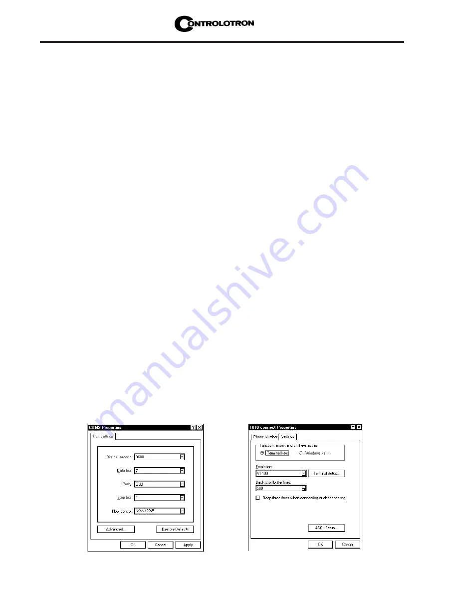
This selects the [Phone Number] dialog box. Move cursor to the arrow at right of [Connect

Using] field. Left click on arrow to expand field and move the highlight down to [Direct to

Com 1 (or 2)] depending on the port connected to the interface cable. Click [OK] to select

[Com 1 (or 2) Properties] Dialog box. Set up your RS-232 parameters as shown (below left).

Left-click on the [OK] button.

You will now see a blank terminal screen. Next click [File] on the top menu bar. Drag the

highlight down to [Properties] and then left-click.

Left-click [Settings] tab. Expand the [Emulation] box by clicking the <Down Arrow> on the

right-hand side. Drag the highlight down to [VT-100] and then left-click to select it as

shown (below right).

Summary of Contents for SITRANS FUH1010PVX

Page 1: ...6 2014 Edition Answers for industry Operating Instructions SITRANS FUH1010 NEMA 7 Compact Interface Detector 7ME3601 1 7ME3601 2 SITRANS F Siemens Hardware ...

Page 2: ......

Page 3: ...IONS The standard 1010X flow computer either requires 100 120 200 VAC or one of three 9 36 VDC power sources for its power input The power input is protected by a GMA 2A fuse F1 Please replace this fuse with the exact type if it becomes necessary to do so This must be connected to Earth Ground Fuse F1 GMA 2A Cable Clamp AC HOT NEU GND DC GND WARNING Do not connect AC or DC power to flowmeter until...

Page 4: ...er 1 Hot Positive Positive Gnd Positive 2 Neutral Negative Gnd Negative Negative 3 Ground Ground Ground Ground Input Power Connector P8 Wiring NOTE Loosen Wire Clamp Screw insert stripped end of wire and then retighten GND GND 3 2 1 HOT DC AC P8 NEU 2 3 1 Connector Mounting Screws Stripped Wire Wire Clamp Screws NOTE Power Supply connector wires should be stripped stranded or solid conductors AWG ...

Page 5: ... and PCB header located on the 1010X 8 I O module Two screws secure the wire plug to the header The connector assembly is fully polarized for fast and easy mating The wire plug accepts stranded or solid conductors of AWG 12 18 To insert a wire into the wire plug strip back the insulation by 0 31 8 mm loosen the wire clamp screw insert the stripped wire end and then re tighten the wire clamp screw ...

Page 6: ......

Page 7: ...era tion is completed Clr Active Memory Use this function to restore opera tion if a severe event e g a violent power surge disrupts system operation Refer to F4 reset procedure in the Operation Instructions manual Clr Save Data Clr Saved Data only appears after pressing Down Arrow in response to Clr Active Memory Answering Yes to Clr Saved Data will erase ALL saved data To invoke in RS 232 serial...

Page 8: ...e to one of the fol lowing An out of range data entry An invalid condition e g overlapping sensors in Reflect Mode If selecting Direct Mode does not resolve review all site setup and sensor installation choices particularly data en tered for the pipe and liquid In Reflect Mode the flow meter detects that the pipe wall signal may impinge upon the liquid signal Use Direct Mode instead Trigger ENTER ...

Page 9: ...Otherwise trigger the Left Arrow to abort theinstallationandconductathor oughinvestigation Low Signal Press ENTER During the Initial Makeup the flow meter decides that a level of the re ceive signal is insufficient for proper operation Attempttoimproveoperatingcon ditions by reinstalling the sensors at a different spacing offset or even at a different location on the pipe Switching from Reflect to...

Page 10: ...he MTYmatic routine automatically during its Initial Make up to estab lish a standard setting for the Empty Pipe alarm This process is normally sufficient for setting this parameter The Empty Pipe Set option list allows you to re invoke MTYmatic use an Actual MTY routine if application conditions allow you to empty and refill the pipe or use the Set Empty routine to set the empty pipe threshold by...

Page 11: ...5B or later This equipment contains components that are susceptible to electrostatic discharge ESD Please observe ESD control measures during the handling and connection process SITRANS FUH1010BX INTERFACE DETECTOR IMPORTANT NOTICE Controlotron is now part of Siemens Industry Inc Industry Automation division CoC Ultrasonic Flow Hauppauge NY 11788 USA Siemens Hardware ...

Page 12: ...Manual Changes NOTE For the latest updates and revisions to this field manual go to http support automation siemens com and check the Product Manual listing ...

Page 13: ...NUAL ADDENDUM Manual Addendum September 2008 Copyright 2008 Siemens Industry Inc All rights reserved Made in the USA 1010FMA 58 Digital Damping Procedure Update For Gas Liquid Flowmeters Siemens Hardware ...

Page 14: ......

Page 15: ...r 2 on the keypad while in the Signal Graph Screen mode MinDamp Command Pressing the 1 key will cause MinDamp to appear on the command line at the lower left hand corner of the screen The number listed to the right of the command code represents the exponent in the FUG1010 exponential averaging routine where the larger the number the greater the digital averaging Pressing the key will increase the...

Page 16: ...r Digital Damping Factor z Close proximity to pressure control valves which may generate in band acoustic noise z Very low acoustic signal levels ALC 40 z High electronic noise from variable frequency drives or other external equipment To access the Digital Damping Control using the Test Facilities Graph Screen proceed as follows 1 To use the Test Facilities Graph Screen you must have a working si...

Page 17: ...w is present such as from a reciprocating compressor or for the purpose of diagnosing transient signal behavior A pulsating flow condition that generates more than 45 degrees of phase jitter will generally cause signal correlation problems when any digital averaging is used In this case it may be necessary to completely eliminate the digital averaging by reducing the Digital Damping Factor to 0 In...

Page 18: ...mode press the 0 key on the keypad MaxDamp Command Pressing the 2 key will bring up the MaxDamp command The function of this parameter is similar to the MinDamp command described above however the two parameters interact in the following manner The MinDamp value must not exceed the MaxDamp value therefore increasing the MinDamp value above the previous MaxDamp value will set both parameters to the...

Page 19: ...amping Factor to a value HIGHER than the default value of 4 may be necessary in cases where the signal to noise ratio SN is found to be unacceptably low 15 1 but only if the noise is determined to be asynchronous i e not associated with the transmit or flowmeter timing circuitry as shown in the signal example above where the baseline noise has a higher frequency than the true liquid signal The fol...

Page 20: ...the Digital Damping reduces asynchronous noise Setting the Digital Damping factor to a value LOWER than the default value of 4 may be justified in cases where pulsating flow is present such as from a reciprocating pump or for the purpose of diagnosing transient signal behavior Apulsating flow condition that generates more than 45 degrees of phase jitter will generally cause signal correlation prob...

Page 21: ...ccessing And Leaving The Menu 1 10 1 11 2 System 1010BX Installation Menu Structure 1 11 1 11 3 How To Use The Magnetic Wand To Enter Data 1 14 How to Select Items from an Option List 1 15 A Note on Multiple Select Option Lists 1 16 How to Enter Numeric Data 1 16 How to Enter Alphanumeric Strings 1 17 1 12 How To Use The RS 232 Interface To Enter Data 1 19 1 12 1 The RS 232 Interface Cable 1 19 1 ...

Page 22: ...ipe Data Menu Structure 2 7 2 2 1 How To Select A Pipe Class 2 8 2 2 2 How To Select A Pipe Size 2 8 2 2 3 How To Enter The Pipe OD in or mm 2 9 2 2 4 How To Select A Pipe Material 2 9 2 2 5 How To Enter The Wall Thickness 2 9 2 2 6 Liner Material 2 10 2 2 7 Liner Thickness 2 10 2 3 The Application Data Menu 2 10 Application Data Menu Structure 2 11 2 3 1 How To Select A Liquid Class 2 12 How to E...

Page 23: ...t Menu 2 30 How to Use the Actual MTY Command 2 30 How to Use the MTYmatic Command 2 30 How to Use the Set Empty Command 2 31 2 5 The Operation Adjust Menu 2 31 2 5 1 Memory Fault Set 2 32 2 5 2 Memory Delay sec 2 32 2 5 3 Sonilocator Operation 2 32 Using the Sonilocate Menu Item 2 33 2 6 The Data Span Set Cal Menu 2 35 The Data Span Set Cal Menu Structure 2 35 2 6 1 Span Data 2 36 Max LiquIdent 2...

Page 24: ...atalogger Setup Menu Structure 2 43 Datalogger Data Option List 2 44 Alarm Letter Codes and Descriptions 2 44 2 7 3 Log Time Interval 2 45 2 7 4 Datalogger Events 2 45 2 8 The I O Data Control Menu 2 46 The I O Data Control Menu Structure 2 46 2 8 1 Analog Out Setup 2 47 System 1010 Analog Outputs 2 47 Analog Out Setup Data Categories 2 47 Assigning Io Output Functions 2 48 Assigning Pgen Output F...

Page 25: ...ount The Transducers 3 4 3 3 1 How To Identify 1011 Transducers And Mounting Hardware 3 4 3 3 2 Selecting A Location For Clamp On Transducers 3 4 3 3 3 Clamp On Transducer Mounting Modes 3 5 3 3 4 Preparing The Pipe 3 6 3 3 5 Sonic Coupling Compound Recommendations 3 7 3 3 6 Reflect Mode With EZ Clamp and Spacer Bar Only 3 8 3 3 7 Direct Mode With EZ Clamp and Spacer Bar Only 3 9 3 3 8 Reflect Mod...

Page 26: ...ate Menu Structure 4 10 4 6 1 The RTD Calibration By Data Entry 4 10 4 6 2 Ice Bath RTD Calibration 4 11 4 7 The Clock Set Menu 4 11 Clock Set Menu Structure 4 11 4 7 1 Date 4 12 4 7 2 Time 4 12 4 8 RS 232 Setup 4 12 RS 232 Menu Structure 4 13 4 8 1 Baud Rate 4 13 4 8 2 Parity 4 13 4 8 3 Data Bits 4 14 4 8 4 Line Feed 4 14 4 8 5 Network ID 4 14 4 8 6 RTS Key Time 4 15 4 9 System Info 4 15 System I...

Page 27: ...sources 5 4 5 10 Reference Tables 5 5 Sonic Velocity m s For Common Liquids 68ºF 5 5 Sonic Velocity For Pure Water Various Temp m s 5 5 Vps Values inches sec For Some Common Metals 5 6 Terminology Chart 5 7 5 11 The Dual Channel Menu Chart 5 9 The Meter Type Menu 5 9 The Meter Facilities Menu 5 9 The Dual Channel Menu 5 10 APPENDICES Appendix A Engineering Drawings A 1 Index Pipe Table vii Siemens...

Page 28: ......

Page 29: ...s perform the installation and wiring It is solely the user s responsibility to operate this equipment safely Controlotron cannot accept responsibility for any damage that may occur due to failure to observe any local safety rules If this equipment is used for a hazardous application high line pressure hostile liquid charac teristics perilous atmosphere etc the end user must ensure that only prope...

Page 30: ... NEMA 7 explosion proof housing z Flexible Setup options using either Magnetic Wand or a PC connected to RS 232 port z Integral 2x16 Character LCD panel display shows real time data and Installation Menu for Magnetic Wand programming z Flexible mounting either on pipe or located up to 300 feet 100m from the transducers For distances greater then 300 feet please contact Controlotron Customer Servic...

Page 31: ...iginal integrity The operating system consists of real time data collection and meter control algorithms and an Installation Menu interface for easy data entry 1 5 1 INSTALLATION MENU OVERVIEW For all System 1010 models site set up is accomplished under the control of an Installation Menu The Installation Menu presents all the site setup options consistent with the meter type to be installed In ot...

Page 32: ...at any time to change the selected flow rate units Note that changing primary site setup data like the pipe outer diameter OD or the transducer model will invalidate the site setup thus requiring a reinstallation 1 6 DESCRIPTION OF CHANNEL FUNCTIONS 1010DBX Systems only Dual channel 1010DBX systems provide two measurement channels that allow its operation as two completely independent single chann...

Page 33: ...RING NOTE Refer to installation drawings 1010BX 7 1 of 3 and 1010BDX 7 1 of 3 WARNING Turn off main power before installing AC connections to the 1010 NEMA flowmeter Contact with exposed wiring may lead to fire electric shock or serious personal injury z Using a 1 16 Hex key loosen the 1010X Rear Housing Cover locking setscrew z Unscrew the Rear Housing Cover and remove z Locate power supply conne...

Page 34: ...option is available see Channel Setup The menu lockout switch S1 resides on the I O module on the right side of I O wiring terminal block TB1 see below Please switch to the unlocked position before attempting to program the flow computer We recommend that the Installation Menu remains locked during normal opera tion NOTE Loosen Wire Clamp Screw insert stripped end of wire and then retighten GND GN...

Page 35: ...Complete transducer install menu operation The figure on the next page shows a simplified 1010BX Interface Detector hardware configu ration with transducers 1 10 CHOOSING A PROGRAMMING INTERFACE As mentioned previously site setup is accomplished under the control of an Installation Menu that allows you to enter information that is specific to each site System 1010BX provides two ways of accessing ...

Page 36: ...0BX INTERFACE DETECTOR SYSTEM RS 232 I O TOP VIEW Pipe Transducer Wiring Enclosure Clamp on Transducers Mounted on side of pipe Connect to Earth Ground LCD Panel Display Power Analog Output Inputs Digital Output Inputs Interface Detector ...

Page 37: ...ated graphic screen displays are identical We recommend this method because it allows you to view the Installation Menu using a 40 Character by 12 line interface In addition it allows you to access System 1010 s comprehensive on line help text The following example screen is an actual HyperTerminal screen capture Refer to paragraph 1 12 for instructions on RS 232 interfacing SYSTEM 1010BX MAGNETIC...

Page 38: ...gnetic Wand tip over the ENTER switch located above the target symbol This accesses the top level of the Installation Menu as shown in the follow ing figure Note that the top line of the LCD display shows the currently selected menu Meter Type and that the second line shows Single Channel preceded by the greater than symbol Triggering the ENTER sensor now would switch the greater than symbol to a ...

Page 39: ...a Pick Pipe Class Select Pipe Size Pipe OD Pipe Material Wall Thickness Liner Material Liner thickness Application Data Liquid Class Liquid Table Temp Range Pipe Config Anomaly Diams Pick Install Xdcr Transducer Model Transducer Size Xdcr Mount Mode Spacing Offset Number Index Spacing Method Ltn Value Install Complete Empty Pipe Set Operation Adjust Memory Fault Set Fault Memory Delay N A SL Rate ...

Page 40: ...erature LowTemperature Areation Makeup Latch InterfaceAlarms ROC Alm Set m s Interval Secs Relay Hold Time High LiquIdent Low LiquIdent Datalogger Setup Datalogger Mode Datalogger Data Log Time Interval Datalogger Events I O Data Control Analog Out Setup Io1 Pgen 1 Relay Setup Relay 1 Analog Inp Setup Iin1 Input Off Aux S G API Kg m3 cS cP PSIA BARA Deg F Deg C 4mA x xxx 20 mA x xxx lin2 see lin1 ...

Page 41: ...TL uSec DeltaT nSec Burst Sec Accepted Last Makeup Makeup Status Liquid Data Temp 1 Temp 2 Liquid Name LiquIdent ROC Specific Gravity API Kg m3 Base S G Base API Base Kg m3 Viscosity cS Pressure Viscosity cP Site Setup Data fx drive N burst length Ltn in Vs max m s Vs min m s Empty Samples Cycle Max Damping Min Damping Test Facilities Makeup Tx Up Tx Dn Fixed ALC Tx Up Fixed ALC Tx Dn Fixed ALC Pr...

Page 42: ... type of data The conven tions used with these instructions are Meter Facilities Table Setups Pipe Table Delete Pipe Choose Pipe Class Pick Pipe Name Transducer Type 1011 Universal 1011 Hi Prec 991 Universal Datalogger Cntrl Output Datalogger No Yes Est Log Time Left Clear Datalogger No Yes Memory Control Data Memory Left Defragment Yes No Analog Output Trim Trim Io 1 Operate Trim 4mA Trim Pgen 1 ...

Page 43: ... the Select Liquid option list Keeping the tip over the sensor activates an auto repeat function to scroll the list automatically Note that ev ery trigger item changes to another liquid on list see paragraph 2 3 for the Select Liquid option list Note that holding down on either the Up or Down Arrow will cause the menu to scroll up or down Auto Repeat Feature z Stop triggering when the screen shows...

Page 44: ...ect a previously selected item scroll to that item marked by an asterisk and then use After selecting all the desired items use to leave a multiple select option list How To Enter Numeric Data This section shows how to edit a numeric menu cell The following example uses the Pipe OD menu cell The left hand figure below shows the Pipe OD menu cell Notice that the second line shows the current outer ...

Page 45: ...n After entering the new value the screen switches to the next menu cell Pipe OD in 0 Pipe OD in 4 Cursor shown at first number position The decimal point shown selected z Use to move cursor to move to the third number position Use to scroll the number list to 5 Use to register the new pipe outer diameter This moves the screen to the next menu cell Pipe Material as shown in the right hand figure a...

Page 46: ...osition Create Name Site SITE1 Site Security Off Screen switches to next menu cell after entering site setup name Cursor shown at fifth character position z With the cursor at the first character position use to scroll through the character list until you see S Use to move the cursor to the second position Use to scroll the list back down to I Use to move the cursor to the third position Use to sc...

Page 47: ...setup procedure for System 1010BX and our graphic display sys tems e g the 1010BN Interface Detector are virtually identical NOTE If you use a DOS based communications program make sure that your PC is loading the ANSI SYS driver via your Config Sys start up file Set the RS 232 parameters to match those of the meter see example of HyperTerminal screen on the next page 1 12 1 THE RS 232 INTERFACE C...

Page 48: ... the START button Holding down the left mouse button move the highlight up to Programs then across to Accessories Slide the highlight down to HyperTerminal then release the left mouse button Within the HyperTerminal window move the mouse pointer down to Hyperterm exe and then double click the left mouse button This selects the Connection Description dialog box Enter a name for your connection e g ...

Page 49: ... a blank area on your desktop Right click to open dialog box and left click on Paste to place a shortcut to the connect icon on your desktop 1 12 3 ACCESSING THE INSTALLATION MENU Once parameters are set HyperTerminal automatically connects with the flow computer when you double click the icon created previously The interface provides three discrete ter minal modes Command mode Installation Menu m...

Page 50: ...rect position Connect the serial interface cable between the flow computer and your laptop computer Run HyperTerminal or your choice of communication program using settings explained previously In Command Mode type menu 1000 press ENT to select the top level of the Installa tion Menu NOTE The first time you access the Installation Menu you can leave it only by saving a site or by turning the meter...

Page 51: ...desirable method since to restore operation all you have to do is reload a saved Site Setup If this fails then you have to use the second level which clears ALL Dynamic Memory Be aware that this action erases all saved Site Setups including flow calibrated sites any logged data and any user defined pipe and transducer tables This will require you to re initialize the meter and transducers and repe...

Page 52: ...n the 16 x 2 Character LCD becomes active The reason for the delay is to give you a chance to perform the following system reset procedure To clear ALL Dynamic Memory using the Magnetic Wand CAUTION Before proceeding further it is essential to understand that this function eliminates ALL data stored in RAM This means that all saved Site Setups including the site data of a flow calibrated site will...

Page 53: ... power type the character three times The prompt Clr Active Memory No appears at the top of the screen Press the Right Arrow and then the Down Arrow to switch the option list to Clr Active Memory Yes Press ENTER to clear all Active Site Data but not saved Site Setups To restore operation press MENU to access the Installation Menu Create a new Site Setup or recall a stored Site Setup Re select any ...

Page 54: ... channel model shows either Channel 1 or Channel 2 EXPLANATIONS OF INSTALLATION MENU CALLOUTS Current Selected Meter Type Site indicates Single Channel Flowmeter operating mode selected Menu Prompt Line When you select a menu cell a reverse text prompt appears on the top of the screen to explain the function of the cell Selected Channel The 1 shows that measurement channel 1 is currently selected ...

Page 55: ...table Menu cells that use these strings provide an 8 character max field for data entry Entering alphanumeric strings are easy since the 1010BX responds to keys typed on your keyboard The following example uses the Create Name Site menu cell This is the first action required to begin a new site setup We will use the site name SITE1 See the screen below Note that the right hand highlight is blank z...

Page 56: ...ur application How to access this menu will be explained later Note that the menu name I O Data Control appears highlighted on the lower left of the screen Note also that the menu cell Relay Setup is highlighted Note that the right hand column has no data at this time Controlotron Site 1 Recall Site Setup No Sites Channel Enable No Create Name Site SITE1 Site Security Off Flow Delete Site Setup No...

Page 57: ...hen you arrive at the last item on a list the next Down Arrow press brings you back to the top of the list This is be cause the option lists are of the wrap around type To select an option list item move the cursor to the item and then press the ENT key This places your selection at the top of the list and moves you out of the option list to the next menu cell Examine the screen below The option l...

Page 58: ...pe Data Application Data Pick Install Xdcr Flow Operation Adjust Data Span Set Cal Datalogger Setup I O Data Control Diagnostic Data Multiple Select Option Lists Certain option lists allow you to make more than one selection For instance the Datalogger Data option list shown on the next page allows you to select any or all of the available data items for your reports You can use the Up and Down Ar...

Page 59: ...ically mounting the transducers on the pipe invoke the Install Transducer procedure This setup is the fastest way to get the meter operational It accepts most defaults and only provides a data output on the local LCD display panel The first step is to create a new site setup NOTE Always begin a new installation by issuing the Create Name Site command This action prepares the flow computer for site...

Page 60: ...d SITE1 as detailed in paragraph 1 16 1 1 17 2 HOW TO ENTER PIPE DATA After creating the site the next step is to enter the Pipe Data The Pipe Data menu allows you to either enter the pipe data manually or select a preset pipe configuration from an option list This section explains how to enter the data manually The two mandatory entries to be entered in this menu are the pipe s Outer Diameter OD ...

Page 61: ...l select Diesel Fuel Press the Left Arrow then press Down Arrow to Application Data Press the Right Arrow to access the Application Data menu Note that the menu cell Liquid Class is highlighted and the default selection Water 20C 68F appears in the right hand column Controlotron Site 1 SITE1 Enter pipe Outer Diameter manually Pick Pipe Class Manual Entry Select Pipe Size N A Pipe OD in 0 500 Pipe ...

Page 62: ...ated Vs m s Water 200C 392F Viscosity cS Water 225C 437F Density SG Water 250C 482F Acetic Acid Alcohol Bromine Carbon Tet Chlorine Diesel Fuel Liquid Class Access Liquid Option List Controlotron 2 Channel 1 SITE1 Select Liquid Diesel Fuel Estimated Vs m s 1377 Viscosity cS 2 30 Density SG 0 000 Liquid Class Initial sonic velocity 1 17 4 HOW TO MANUALLY SELECT TRANSDUCERS AND A MOUNTING MODE In th...

Page 63: ...Invalid Ltn Value Invalid Install Complete No Empty Pipe Set Chan Not Setup Scroll List and select desired Model Pick Install Xdcr Transducer Model 1011 Universal Transducer Size 1011H Hi Prec Xdcr Mount Mode 991 Universal Spacing Offset Invalid Flow Number Index Invalid Spacing Method Invalid Ltn Value Invalid Install Complete No Empty Pipe Set Chan Not Setup Controlotron 2 Channel 1 SITE1 Scroll...

Page 64: ... press the ENTER key to make the selection The trans ducer Number Index and Ltn values are automatically recomputed in response to any changes you make to the previous selection Installing The Transducers You now have to mount the transducers in accordance with the indexes recommended on the screen Be sure you do not install your transducers backwards or reverse the Upstream and Downstream cables ...

Page 65: ...er hand when the Measured Vs conforms to the Actual Vs your degree of confidence in the correctness of the installation and the meter s intrinsic calibration perfor mance should be high z This commands the meter to re calculate its timing parameters to accommodate the new sonic velocity setting Controlotron 2 Channel 1 SITE1 Controlotron 2 Channel 1 SITE1 Transducer Model 1011H Hi Prec Transducer ...

Page 66: ...that the meter has accepted the new Vs setting Controlotron 2 Channel 1 SITE1 Transducer Model 1011H Hi Prec Transducer Size C1H Xdcr Mount Mode Reflect Spacing Offset Nominal Flow Number Index 24 Spacing Method Spacer Bar 1012BP Ltn Value 2 330 Install Complete Install Empty Pipe Set Chan Not Setup Drive 53 0 36 6 0 Pick Install Xdcr ...

Page 67: ... etc Each menu includes an image of its main screen and a diagram of its structure The rightmost column of the structure diagram lists the option list choices of the menu cell if applicable Review of Installation Menu Notes If a power failure occurs while you are entering or editing data the entered data may not be retained in Active Memory Although you can operate the meter immediately after comp...

Page 68: ...otron 2 Channel 1 XYZ Recall Site XYZ Channel Enable Yes Create Name Site 1 Site Security Off Flow Delete Site Setup 1 Save Rename Site 1 Scroll saved Site Setup list and Enter Channel Setup Use this menu cell to free up site storage memory by deleting obsolete site setups Note that the cell retains the name of the most recently created site setup XYZ This option list expands as you save more site...

Page 69: ...r routine 2 1 2 HOW TO ENABLE AND DISABLE A MEASUREMENT CHANNEL The computer disables a measurement channel until the completion of the required Site Setup entries and the transducer installation procedure The meter enables the measurement chan nel automatically after it receives all required site data and completes the transducer install routine The Site Enable menu cell allows you to disable or ...

Page 70: ...new Site Setup To create the new Site Setup press NOTE If you decide to use numbers or a decimal point in the site name you can type these characters directly from the PC keyboard 2 1 4 HOW TO ENABLE DISABLE SITE SECURITY With Site Security enabled the meter will require a password before it allows any activity that could interrupt or affect system operation You can still access the Installation M...

Page 71: ...e Setup to clear memory space Note that Datalogger storage and Site Storage share a common memory pool Therefore a large amount of logged data could also trigger the Memory Full message See Meter Facilities Datalogger Control for instruc tions on how to clear Datalogger memory Using the Defragment Command may also allow additional sites to be stored see Meter Facility Memory Control Menu To delete...

Page 72: ...e outer diameter OD and wall thick ness to operate You must define these parameters to complete the installation The pipe table includes descriptions for over sixty standard pipes plus any user entered pipes see Meter Facilities To use these presets first pick a Pipe Class e g ASA Stainless Steel then pick a pipe size within that class e g 4SS10 When you select a particular pipe class size the rel...

Page 73: ...00 DN 6CS40 6P40 200 DN 6CS80 6P80 400 DN 8CS40 8P40 800 DN 8CS80 8P80 Metric SGP Steel 10CS XSteel 10P XS 20A SGP 10CS40 10P40 25A SGP 12CS STD 12P STD 32A SGP 12CS XS 12P XS 40A SGP 16CS STD 16P STD 50A SGP 16CS XS 16P XS 65A SGP 18CS STD 18P STD 80A SGP 18CS XS 18P XS 90A SGP 20CS STD 20P STD 100A SGP 20CS XS 20P XS 125A SGP 24CS STD 24P STD 150A SGP 24CS XS 24P XS 175A SGP 30CS STD 30P STD 200...

Page 74: ...e required pipe information You can also select a pipe class size then edit any of the associated defaults to fine tune the pipe data NOTE Create custom pipe data via the Pipe Table editor in the Meter Facilities menu 2 2 2 HOW TO SELECT A PIPE SIZE Selecting a Pipe Size installs the selected pipe parameters into the balance of the Pipe Data menu cells and prepares the 1010BX for Transducer select...

Page 75: ...ection affects flow calibration to a small degree It also influences the meter generated transducer size and spacing recommendations Select a substitute material if you do not find the material of your pipe in the pipe table You can edit each pipe paramet er to achieve a closer match If you change any pipe parameters after running the Trans ducer Install procedure you may have to re space the tran...

Page 76: ...s to the next two menu cells The Liner Material option list offers a selection of common liner materials To select a Liner Material To access the Liner Material option list press To scroll to the required Liner Material press To register selection press 2 2 7 LINER THICKNESS If you specified a pipe liner in the Liner Material menu cell then use this menu cell to set its exact thickness in appropri...

Page 77: ...257F Water 150C 302F Water 175C 347F Water 200C 392F Water 225C 437F Water 250C 482F Acetic Acid Alcohol Bromine Carbon Tet Chlorine Diesel Fuel Gasoline Glycerine Kerosene MEK Oil SAE 20 Sea Water Toluene Trichloroethyl Other Estimated Vs m s xxxx numeric entry Viscosity cS x xx numeric entry Density S G x xxx numeric entry Liquid Class Water 20C 68F Liquid Table Temp Range 40F to 250F Pipe Confi...

Page 78: ... chances of a re spacing request for clamp on flow transducers during the install procedure Use this menu cell to edit the liquid viscosity ONLY if you are certain that the data you enter is accurate An erroneous entry could affect meter calibration Use this menu cell to edit the specific gravity of the liquid Liquid Table TableActive No Yes LiquIdent Slope x xxx numeric entry Pressure Slope x xxx...

Page 79: ...ers during the transducer install procedure ENT NOTE During the Xdcr install procedure see paragraph 2 4 you can ignore a respacing request by pressing the Down Arrow instead of ENT If this triggers a Spacing Alarm check Diagnostic Data Site Setup Data to make sure the measured Vs value does not exceed the Vs max or Vs min items To edit the Estimated Vs m s To activate numeric entry press Using PC...

Page 80: ...ate the measured LiquIdent variable temperature com pensation sonic velocity with user supplied SG and Viscosity By selecting the Liquid Table you can set the LiquIdent Slope Pressure Slope fixed reference Base Temperature K0 and K1 thermal expansion parameters and the LiquIdent Index ENT To activate the Liquid Table menu Press to move the cursor to the Liquid Table menu cell Use to select No or Y...

Page 81: ...default To calculate a liquid s LiquIdent Slope Factor Establish the maximum Tmax and minimum Tmin operating temperatures for all liquids within the Liquid Class For each liquid note the measured sonic velocity located in the Diagnostic Menu at Tmax and the sonic velocity at Tmin in meters per second Use the following formula to calculate the LiquIdent Slope Factors with the Liquid Class LiquIdent...

Page 82: ...e Base Temperature The System 1010 Interface Detector uses a reference Base Temperature of 60ºF 15 6ºC for the LiquIdent Slope Pressure Slope and other settings Any temperature can be entered and used as the reference Base Temperature e g 68ºF 20ºC To enter the Base Temperature From the Liquid Table menu cell press to scroll down to Base Temperature Press to enable numeric entry Use PC numeric key...

Page 83: ...e LiquIdent Index To create a LiquIdent Index Scale for the Liquid Class a minimum of two LiquIdent Indi ces are required to be entered If desired up to sixteen LiquIdent Indices can be entered However the computer only needs two to establish a scale of all the possible LiquIdent indices for the Liquid Class After the computer interpolates the LiquIdent Index Scale its projections can be checked b...

Page 84: ...ure The default value 0 0287 has been found to be adequate for many hydrocarbons Liquid Name You may install a name here if you wish to identify the liquid in the meter s datalogger report To prevent flicker of two names when the LiquIdent is at transition points you may wish to create ranges of LiquIdent and additional entries in between with no name installed K0 and K1 These variables also found...

Page 85: ...ONFIGURATION The Pipe Configuration menu cell in the Application Data menu presents a list of descrip tions of piping configurations that could affect the flow profile characteristics such as Single Elbow Examine the option list Selecting a piping configuration that closely approximates conditions at or near your mounting location allows the flow computer to compensate for the effect of upstream p...

Page 86: ...t most accurately represents the upstream pipe condition PIPE CONFIGURATION OPTION LIST DEFINITIONS Fully Developed Fully Developed flow as would be expected for very long straight pipe runs or installation downstream of a flow condition 1 Elbow Single 90 degree Elbow upstream of transducer installation Dbl Elbow Double out of plane Elbows upstream of transducer installation Dble Elbow Double in p...

Page 87: ...Path 1 Transducer Model 991 Universal Transducer Size 3 Xdcr Mount Mode Direct Spacing Offset 3 Number Index 1 Spacing Method Track 3 Ltn Value 0 939 Install Complete Yes Empty Pipe Set MTYmatic Once you select the type use this menu cell to specify the transducer size This menu cell shows the actual spacing distance required between the transducers This menu cell identifies the spacing index on t...

Page 88: ...INSTALL XDCR MENU STRUCTURE NOTE It would probably be most beneficial to you at this point to read Section 3 before proceeding to mount transducers NOTE When installing transducers do not key in the V M Version Modification label number as the Transducer Size However you can edit the menu entries as required to accommodate different transducers or mounting configurations The Interface Detector wil...

Page 89: ...ve the cursor to Transducer Size the highlighted prompt at the top of the display screen shows a list of recommended transducer sizes For example Recom mended Xdcrs D3 D2 D1 C1 C3 The Interface Detector generates this list automatically based on your pipe and your application data entries The left most transducer size e g D3 is the primary most appropriate choice The rightmost transducer e g C3 is...

Page 90: ...lightly decreased zero flow stability If the computer reports Use Ltn you have to measure the distance between the upstream and downstream transducers The computer issues the actual distance between the transduc ers in inches or millimeters see Ltn paragraph 2 4 8 Please consult Section 3 for details on how to use the Ltn measurement Note that even though using Ltn does not call for the physi cal ...

Page 91: ...ust be determined e g 1011 Transducers in Direct Mode the Inter face Detector issues the actual distance between the transducers in inches or millimeters Ltn Please review Section 3 for details on how to use the Ltn measurement NOTE You must connect the Up Transducer cable to the transducer mounted on the upstream end of the mounting track It is important that you note each transducer s serial num...

Page 92: ...sducers as required see Section 3 for procedures After transducers are properly mounted the meter completes its Initial Makeup command and the Install Complete menu cell appears To access the Install Complete option list press the Right Arrow Press Down Arrow and scroll to the Install Complete menu cell and then press ENT Press ENT The Install Complete menu cell will indicate Yes after the 1010BX ...

Page 93: ...stic software routine allows the user to force a transmitting condition that can be use to search for an amplitude level ALC when Detection Fault or Low Signal alarms are present The routine forces the flowmeter to generate constant transmit bursts while report ing current receive signal strength for the user To initiate the Force Transmit function refer to the example that follows 1 On a PC after...

Page 94: ... only when using a PC via the RS 232 port and indicates the current ALC e g 50 Steps 1 and 2 above must be completed before the meter scans through all the drives or selection of the detection mode and the Force Transmit function must be initiated again NOTE The 1010BX meter does not display the Force Transmit data display line This ALC number indicates the current receive signal strength and can ...

Page 95: ...t In other words entering incorrect pipe parameters or not using the recommended spacing could result in an erroneous Vs measurement The meter is now ready to report flow Press MENU key to display flow In cases where the actual Vs differs noticeably from the estimated Vs the computer may issue a re space command This requires that you re space the Number Index transducer at the new Number Index th...

Page 96: ...Pipe Set option list press To move the cursor to Actual MTY press then press Empty the pipe completely then press appears on the menu prompt line Refill the pipe completely then press How to Use the MTYmatic Command You can repeat MTYmatic performed during the Initial Makeup to correct an inaccurate actual MTY setting if conditions did not allow you to complete the Actual Empty procedure NOTE Only...

Page 97: ...u use it after the transducers are installed and operating to fine tune the meter s output characteristics Each application presents different data display and output requirements due to unique pipe and liquid conditions Use the Operation Adjust menu to match meter operation to the site You can also select the meter response to a continuous fault condition ENT ENT OperationAdjust Memory Fault Set ...

Page 98: ...es the suppressed Memory Delay menu cell It allows you to specify the number of seconds that the meter maintains its last valid reading When the memory delay expires it triggers the fault alarm response described previously To specify the Memory delay To enable numeric entry press Use PC numeric keys or Magnetic Wand to type the delay in seconds To register the new value press 2 5 3 SONILOCATOR OP...

Page 99: ... function is only operational with a Controlotron Master Sta tion and System 1010 meter To access the Sonilocator function proceed as follows At the Meter Type Menu press the Right Arrow key and then ENT to select the desired Path e g Dual Path Flow In the Dual Path Flow Menu press the Down Arrow key Scroll to the Operation Adjust menu cell Press the Right Arrow to select it Controlotron Dual Path...

Page 100: ...a menu cell Press the Right Arrow key to highlight Datalogger Data option list items Press the Up Down Arrow key and scroll to the Sonilocate menu item Press the ENT key to select it A sign will appear to the left of the menu item If desired press CLR key to deselect menu item Continually press the Left Arrow key to return to the main menu Controlotron Dual Path BCD Datalogger Mode Off Datalogger ...

Page 101: ...ry High Kg m3 x xxx numeric entry Low Kg m3 x xxx numeric entry High Base S G x xxx numeric entry Low Base S G x xxx numeric entry High Base API x xxx numeric entry Low Base API x xxx numeric entry High Base Kg m3 x xxx numeric entry Low Base Kg m3 x xxx numeric entry Hi Viscosity cS x xxx numeric entry Low Viscosity cS x xxx numeric entry High Temperature x xxx numeric entry Low Temperature x xxx...

Page 102: ...ess Min LiquIdent The Min LiquIdent menu cell stores the minimum range value for the LiquIdent function To set the Min LiquIdent range setting To activate numeric entry press Use numeric keys or Magnetic Wand to enter the minimum range 0 of range To store data press ENT ENT The following Span Data items are set in the same way as the two previously shown examples by entering numeric values and sto...

Page 103: ... API menu cell stores the maximum range for the API number analog span Min API The Min API menu cell stores the minimum range for the API number analog span Max Kg m3 The Max Kg m3 menu cell stores the maximum range of kilograms per cubic meter analog span Min Kg m3 The Min Kg m3 menu cell stores the minimum range of kilograms per cubic meter analog span Max Base S G The Max Base S G menu cell sto...

Page 104: ...l be in Fahrenheit Min Temperature The Min Temperature menu cell stores the minimum temperature range for the analog span If metric units are selected for pipe O D etc the temperature units will be in Centigrade If English units are selected the temperature will be in Fahrenheit 2 6 2 SET ALARMS The Alarm Setpoints menu allows you to select system alarm functions Alarms appear locally on the LCD d...

Page 105: ...API number analog span High Kg m3 The High Kg m3 menu cell sets the high alarm relay setpoint for the kilograms per cubic meter analog span Low Kg m3 The Low Kg m3 menu cell sets the low alarm relay setpoint for the kilograms per cubic meter analog span High Base S G The High Base S G menu cell sets the high alarm relay setpoint for the Specific Gravity of a liquid at base temperature Low Base S G...

Page 106: ...If English units are selected the temperature will be in Fahrenheit Aeration The 1010BX surpasses all other transit time systems in its ability to operate with substantial aeration caused by entrained gases mixing condition or cavitation Some applications may require an alarm indication if aeration exceeds a particular level The meter detects this aera tion level and provides this data as an outpu...

Page 107: ...ing To turn Makeup Latch On or Off press 2 6 3 INTERFACE ALARMS The Interface Alarms menu cell is selected to monitor the sonic velocity Vs It is a constant rate of change alarm function that monitors the LiquIdent setting The alarms appear locally on the LCD digital display ROC Alm Set m s Use the Roc Alm Set m s menu item to set the desired numerical alarm relay setpoint in meters per second For...

Page 108: ...MENU This menu becomes available after picking Meter Type and Measurement Channel The inte gral Datalogger records data via a RS 232 compatible external device printer computer net work etc Use Datalogger Setup to select data items and real time events for datalogger reports You can also set the logging interval operating mode and screen format The Datalogger Setup menu allows you to choose time i...

Page 109: ...7 2 DATALOGGER DATA Set the Datalogger to record any or all of the data offered on the Datalogger Data option list shown below However recording unneeded data wastes valuable system RAM We recom mend that you always select Site ID name and Time to identify each line of data ENT Datalogger Setup Datalogger Mode Off Memory RS 232 Output Datalogger Data None Site Id Date Time Raw Path Vs Vs Path Valc...

Page 110: ...he time of the report Aeration The aeration percentage recorded at the time of the report Path Alarms The letter codes of any Path related alarms at the time of the report Alarms The letter codes of any alarms active at the time of the report see below S G Specific Gravity at current operating temperature Base S G Specific Gravity referenced to user selected temperature API API number at current o...

Page 111: ... imme diately after the transition from a non alarm to an alarm event The reverse situation alarm state to non alarm state does not trigger the event based Datalogger Event based Datalogger messages conserve memory However if you use this feature to monitor a level such as Interface Alarm set the alarm threshold high enough to avoid repetitive trig gering You must select Site ID Name and Time to t...

Page 112: ...hat this removes the plus sign from the item After selecting all desired items press to leave the Datalogger Events option list CLR Analog Output Setup Relay Setup Analog Inp Setup Controlotron Dual Path SITE 1 Assign Data to Analog Outputs I O Data Control Use this menu to assign data functions to Analog Outputs Use this menu to assign alarm functions to relay outputs Use this menu to enable and ...

Page 113: ...e kg m3 Hi Temperature Low Temperature Fault Alarm Spacing Empty Areation ROC Off Relay 2 See Relay 1 Analog Inp Setup Iin1 2 Input Off Aux SG API Kg m3 cS cP PSIA BARA Deg F Deg C 4 mA numeric entry 20 mA numeric entry THE I O DATA CONTROL MENU STRUCTURE continued LiquIdent m s System sonic velocity compensated for temperature SG Current liquid specific gravity API Current liquid API number Kg m3...

Page 114: ...ut To access the Pgen option list press Move the cursor to the desired data function by pressing To store selection press 2 8 2 RELAY SETUP Use this menu to assign a function to channel relays System 1010 supports 2 types of re lay outputs Alarm Relay and Pulse Relay Alarm Relay outputs operate in fail safe mode The relay s are energized under normal conditions an alarm condition causes the relay ...

Page 115: ...API number relay trip point High SG High Specific Gravity value relay trip point Low SG Low Specific Gravity value relay trip point High Base API High API relay trip point at reference temperature Low Base API Low API relay trip point at reference temperature High Base SG High SG value relay trip point at reference temperature Low Base SG Low SG value relay trip point at reference temperature High...

Page 116: ... To store the data press Repeat for other Analog Inputs as desired 2 8 3 ANALOG INPUT SETUP optional function The Analog Input Setup function assigns an active analog input to a measurement channel path The meter provides four DC current input ports for single channel or Dual Channel units The DC current input ranges from a zero level of 4 mA to a full scale of 20 mA The Analog Input Setup menu ce...

Page 117: ...c items are available for Path 1 or Path 2 Some items are not available N A when you select the virtual Channel 3 In addition selecting virtual Channel 3 in either the 1 2 or 1 2 modes will limit the list Diagnostic Data Path Select 1 2 Path Enable N A Siganl Data Vs m s Signal mV Valc Vaer Alarm Status Application Info TN uSec TL uSec DeltaT nSec Burst Sec Accepted Last Makeup Makeup Status Liqui...

Page 118: ...ath Enable Controlotron Dual Path SITE 1 Select Diagonostics Data Display Source Signal Data Application Info Liquid Data Site Setup Data Test Facililties Print Site Setup No Date Site Created 08 11 9911 99 12 48 58 I O Data Control Path Select This meau allows selection of Path 1 or Path 2 Path Enable This menu enables the selected Path Signal Data This menu shows Signal specific data Application...

Page 119: ...educed accuracy Signal mV Xdcr signal strength in mV This is the amplitude of the transit time receive signals Improper coupling attenuative liquid or pipe could cause a low value Valc Input Amplifier gain indication Larger indicates a stronger liquid signal Vaer This shows the current percent of aeration detected by the meter Alarm Status This letter code field shows the status of the meter s bui...

Page 120: ... touch the Right Arrow sensor with the magnetic wand The pipe diameter and transmission frequency determines the effec tive increase or decrease per key press Sonic velocity Vs adjustment is a diagnostic tool intended for our technicians or experienced users only Improper use will affect the meter accuracy AnCal This menu cell allows you to enter an artificial rate in current rate units that will ...

Page 121: ...wing factors influence this parameter aeration pressure trans ients signal strength variation Accepted The percentage of accepted up down transmit burst sets Last Makeup Reason for last Makeup signal reacquisition Press the meter s Help key at this menu cell to see a glossary of all the possible reasons for a Makeup Makeup Status Current stage of Makeup routine Measurement normal operation TN uSec...

Page 122: ...etered cubed relative to base temperature of liquid Viscosity cS Kinematic viscosity of a liquid measured in centistokes Pressure Merasured pressure Viscosity cP The absolute viscosity of a liquid dynamically measured in centipoise LIQUID DATA MENU ITEMS fx drive Current Transmit drive code selected during Initial Makeup The drive code controls the sonic transmit signal N burst length Transmit bur...

Page 123: ...smission only Fixed ALC Select Yes to command amplifier to hold a constant gain TX Up Fixed ALC Fixed ALC while transmitting up only TX Dn Fixed ALC Fixed ALC while transmitting down only Force Transmit Transmits burst while measuring Valc For diagnostic purposes only Not displayed as menu cell Force Frequency Not displayed as a menu cell For technical service diagnostics TEST FACILITIES COMMANDS ...

Page 124: ...explana tions and in some cases a recommended action Makeup The Test Facilities Menu Makeup routine allows you to command the meter to re acquire the operating parameters established during the Initial Makeup routine invoked by the Install Completed command see paragraph 2 4 Pick Install Xdcr To invoke the Makeup routine Press to scroll the cursor to Makeup Press to access the test option list Pre...

Page 125: ...If selecting Direct Mode does not resolve review all site setup and transducer installation choices particularly data entered for the pipe and liquid In Reflect Mode the flow computer detects that the pipe wall signal may infringe upon the liquid signal Use Direct Mode instead Press ENT UP Arrow DOWN Arrow or LEFT Arrow to abort install routine Continue programming other site data in antici pation...

Page 126: ...ecommended that you contact Technical Service for further orientation 2 10 2 TROUBLESHOOTING WITH TRANSDUCER TEST BLOCKS To resolve an apparent system malfunction you have to determine whether the problem is due to equipment failure or an application condition Our 1012 and 996 Transducer Test Blocks allow you to bench test the 1010BX transducers and their cables If the system operates prop erly us...

Page 127: ...cer size under test Part Xdcr Pipe OD Pipe Wall Mount Spacing Number Number Size in Mat l Thk in Mode Offset Index 1012TB 1 A 0 650 Steel 0 100 Reflect Nominal 7 1012TB 1 B 1 150 Steel 0 100 Direct Minimum 4 1012TB 2 C 2 000 Steel 0 100 Reflect Nominal 11 1012TB 2 D 3 500 Steel 0 100 Direct Minimum Use Ltn 1012TB 1 2 Universal Transducer Test Block Chart English System Default 1012TB 1 A 16 5 Stee...

Page 128: ...e Name Site Create a new Site Setup e g TEST1 You can now enter data without altering an existing Site Setup Select the Pipe Data Menu Referencing either the English or metric pipe simulator chart below enter the pipe parameters corresponding to the transducer size under test Upon the completion of the Install procedure the computer should report a sonic velo city within the range of approximately...

Page 129: ...blem If a Pipe Simulator Test Block Test Fails Replace the transducer cables If this allows you to complete the test as described above then the cables were defective If the cables are proven to be good replace the transducers on the pipe simulator with a known good set If the system functions properly then the original transducers under test are defective Please return any defective transducers t...

Page 130: ......

Page 131: ... Note that the assembly includes a mounting bracket with four bolt holes Please refer to Engi neering Drawing 1010BX 8 in Appendix B of this field manual for outline dimensions etc NOTE All enclosure lids are secured with set screws This is required to maintain the explosion proof ratings You will need a 1 16 hex key to remove and replace enclosure lids STANDARD UPRIGHT MOUNTING Front Housing Cove...

Page 132: ...SOLATED LOOP SUPPLY Spannable 4 20mA output proportional to any available data variable assigned under menu control 5 ANIN 2 ANALOG IN CH 2 6 ANIN 1 ANALOG IN CH 1 Receives 4 20mA input from external instrumentation Optional function depends on specific 1010BX model Use RS 232 ground for return 7 STATUS CH1 STATUS BIT RETURN 8 STATUS CH1 STATUS OUTPUT Status output responds to any available alarm ...

Page 133: ...PLY Spannable 4 20mA output proportional to any available data variable assigned under menu control 5 ANIN 2 ANALOG IN CH 2 6 ANIN 1 ANALOG IN CH 1 Receives 4 20mA input from external instrumentation Optional function depends on specific 1010BX model Use RS 232 ground for return 7 STATUS CH1 STATUS BIT RETURN 8 STATUS CH1 STATUS OUTPUT Status output responds to any available alarm CH 1 function as...

Page 134: ...O IDENTIFY 1011 TRANSDUCERS AND MOUNTING HARDWARE 1011 series of universal transducers and mounting frames have the following color codes for easy identification GOLD SIZE A GREEN SIZE D BLUE SIZE B BLACK SIZE E RED SIZE C The transducer part number located on the front face provides a more detailed identification For example the Part Number 1011PPS C2 means 3 3 2 SELECTING A LOCATION FOR CLAMP ON...

Page 135: ...ducer at nine o clock and one transducer at three o clock for Direct Mode Mounting on a vertical pipe is recommended only if flow is in the upward direction When mounting on a vertical pipe flowing in a downward direction make sure there is sufficient back pressure in the system to maintain a full pipe 3 3 3 CLAMP ON TRANSDUCER MOUNTING MODES Controlotron clamp on transducers support Direct or Ref...

Page 136: ...ucer Sonic Path Pipe Downstream Transducer 1234567890 1234567890 1234567890 1234567890 123456789 123456789 123456789 123456789 Cleaned areas Clean an area 1 2 on either side of transducer and an additional 1 2 along the length of the transducer Pipe PREPARING THE PIPE SURFACE 3 3 4 PREPARING THE PIPE Pick a mounting location You must have easy access to at least one side of your pipe The mounting ...

Page 137: ...ge 255 F to 450 F temperatures 5 111 Permanent high temp couplant for plastic flow Room temperature vulcan transducers Temp range 255 F to 450 F izing silicone rubber 6 112 Permanent ambient temperature couplant for Room temperature vulcan plastic flow transducers Temp range 40 F izing silicone rubber to 250 F 7 113 Protective spray for providing corrosion resis Spray on liquid Excellent tance to ...

Page 138: ... cable connectors facing away from each other as shown above The spacer bar is attached to a transducer using a transducer index screw One transducer is attached using the REF hole on the spacer bar The sec ond transducer is attached to the spacer at the index hole specified in Step 1 Note that in some cases the transducers may have two sets of holes for securing the transducers When using the EZ ...

Page 139: ...compound to the transducer At the same time that you place it in the middle of the second area prepared secure the spacing bar to the already mounted transducer by inserting the transducer index screw through the REF hole on the Bar and into lowest hole on transducer for those transducers that have two holes Sight along spacer bar to ensure axial alignment to the pipe Adjust if necessary Tighten b...

Page 140: ... Temporarily position one transducer in the 9 o clock position at the location where you have determined it would be mounted Ensure that this is a smooth area without any raised spots seams etc Mark a generous area around the transducer where it contacts the pipe with a pencil or chalk Remove the transducer 3 Prepare the area you marked by de greasing the surface if needed and removing any grit co...

Page 141: ... in paragraph 1 Note that in some cases the transducers may have two sets of holes for securing the spacer bar When using the EZ clamp assembly use the lower set of holes when attaching the spacer bar 8 Unlike the first transducer do not apply any couplant at this point Attach the spacer bar with the second transducer attached to it to the mounted transducer by inserting an in dex screw through th...

Page 142: ...sducer and the Mylar guide 13 Prepare the area you marked by de greasing the surface if needed and removing any grit corrosion rust loose paint or surface irregularities with the abrasive pipe conditioning material provided 14 Replace the Mylar guide back in the same position it was in and retape it to the pipe Attach the EZ clamp to the transducer under the spring clip Unscrew the knob until it s...

Page 143: ...played in the Pick Install menu You will use this number to properly space the transducers Check to ensure that you have a matched set of transducers They both should have the same S N number but marked with either an A or B e g 100A and 100B INSTALLATION REFLECT MOUNT WITH FRAMES AND SPACER BAR NOTE Minimum Ltn 0 75 in 18 mm Mounting Strap positioned around Mounting Frame Mounting Strap Adjusting...

Page 144: ...ttach the other ends to the flowmeter s UP and DN terminals See Engineer ing Drawing 1010BX 7 Single Channel or 1010BDX 7 Dual Channel 7 You can now press ENT to finish the transducer install routine The available Mounting Strap kits are listed below Each kit comes with up to two band sizes to cover its designated pipe diameter range and a spacing guide for Direct Mount 2 On a flat surface attach ...

Page 145: ...sing the surface if needed and removing any grit corrosion rust loose paint or surface irregularities with the abrasive pipe condition ing material provided Clean the pipe of all debris and abrasive particles 5 Remove transducer from the spacer bar that was attached through the REF hole Put a mounting strap around the pipe and engage an end into the adjusting screw adjusting screw should be pointi...

Page 146: ...he combination of mounting frames spacer bar and spacing guides is the recommended way to mount Direct Mode transducers The mounting frame establishes the axial alignment of the transducers and allows you to remove and replace either transducer while preserving their exact mounting location For Direct Mode mounting you will use a spacer bar to establish the distance between trans ducers and a spac...

Page 147: ... and engage an end into adjusting screw screw should be pointing up Position frame in the middle of area you have cleaned and cen tered on the pipe with its angled end facing away from where the other frame will sit WRAPPING STRAP UNDER PIPE AND ATTACHING TO ADJUSTING SCREW 5 Slide the mounting strap over it and under the clip if there is one and tighten with a screwdriver While tightening check t...

Page 148: ...o fit if necessary but in order to keep it square be sure not to trim at the overlapping end 9 Realign left edge of the guide with the transducer edge mark Line up both vertical edges of the guide and ensuring that it is snug around the pipe mark along the overlapping edge 10 Remove Mylar spacing guide and lay it out on a flat surface Either measure the exact distance halfway between the overlap e...

Page 149: ...uld be pointing up Position frame in the middle of area you have cleaned and centered on the pipe with its angled end facing away from where the other frame will sit and aligned with the edge and center marks on the guide Slide the mounting strap over it and under the clip if there is one and tighten with a screwdriver While tightening check to ensure that the center of the tapered roller is cente...

Page 150: ...ck in Reflect Mode Paragraph 2 4 describes the Transducer Installation procedures that lead up to the automatic selection of transducers mounting mode and spacing method Examine the figure below which shows a typical Pick Install Xdcr menu screen Note the automatic assignment of model num bers for the transducer and mounting track plus the designation of the number index This example requires a Mo...

Page 151: ...1 2 inch on either side and half again the length front and back with a pencil or chalk Loosen and move the assembly away from marked area Prepare the two areas you marked by de greasing the surface if needed and removing any grit corrosion rust loose paint or surface irregularities with the abrasive pipe conditioning material provided Clean the pipe of all debris and abrasive particles 4 Insert t...

Page 152: ...you to press to finish the transducer install routine Note the reported number index You will be inserting an index pin into this hole and the reference hole Check to ensure that you have a matched set of transducers They both should have the same S N number but marked with either an A or B e g 100A and 100B 2 The Direct mount configuration uses two track rails one for each transducer installed 18...

Page 153: ...n Move the transducer right until the pin stops it Hold it in this position and move the transducer clamping screw over the trans ducer and tighten Insert the other index pin into the index hole see step 1 on the other track marked Direct Mode Spacing Insert the second transducer with its cable connec tor pointing away from the pin between the track rails on the right side of the pin and move the ...

Page 154: ...pe and sensor after clamp on installation is complete 3 4 2 991TW THERMOWELL TEMPERATURE SENSOR The 991TW insert sensors are designed to be used in pipes equipped with Thermowells These are spring loaded 1 4 inch diameter sensors with 1 2 inch NPT integral connection heads available in several lengths to accommodate a range of pipe sizes Thermowells for new instal lations are available from Alloy ...

Page 155: ... tracking of the true liquid tem perature try to make your installation conform to the notes on the installation drawing and these following tips Prepare the pipe surface by removing paint to expose bare metal and by smoothing out any remaining rough spots 3 5 NOTES ON SYSTEM 1010 ANALOG INPUT MODULES Single Channel Models System 1010 meters report input module temperature sensor connections T1 an...

Page 156: ...ure sensing The foam insulator supplied helps in this regard but consider using additional pipe insulation for all installations exposed to extreme ambient conditions Consider mounting the RTD under the pipe in order to keep it out of direct sunlight In installations where RTD elements are exposed to harsh conditions such as condensation salt spray etc use CC 110 couplant compound to coat the conn...

Page 157: ... for all menu items and data outputs You can choose either English or metric units The factory setting is English To specify metric default units for all meter functions To access the Preferred Units option list press Press to move the cursor to Metric menu cell To register your selection press ENT This menu allows you to specify default measurement units This menu allows you to create or edit pip...

Page 158: ...s by loading all required data at once from option list selection The Pipe Table configuration is PIPE CLASS Î PIPE NAME Pipe Class presents a list of standard metric and English Pipe classifications Selecting a class e g ASA Carbon Steel conditions the Pipe Name option list to all the stored pipes within that class see Menu Chart above Selecting a pipe by its name e g 2SS10 loads a description of...

Page 159: ... XS 20P XS 125A SGP 24CS STD 24P STD 150A SGP 24CS XS 24P XS 175A SGP 30CS STD 30P STD 200A SGP 30CS XS 30P XS 225A SGP 36CS STD 36P STD 250A SGP 36CS XS 36P XS 300A SGP Cast Iron Table Copper Tube Table 350A SGP 6 cls C 1 type M 400A SGP 10 cls C 1 type K 450A SGP 12 cls C 1 type L 500A SGP 16 cls C 2 type M 20 cls C 2 type K Ductile Iron Table 2 type L 6 cls 52 4 type M 8 cls 52 4 type K 10 cls ...

Page 160: ...sts the name of the selected pipe Press and then press to use this name To use a new name press and then use the appropriate arrow keys to rename the pipe 8 characters Max Press This adds the new pipe to the pipe class 4 2 3 DELETE PIPE This menu allows you to remove any of the pre loaded pipes within a class from pipe table To preserve the factory presets we recommend that you use this function o...

Page 161: ...to a transducer type e g 1011H High Precision then press to access the size option list Scroll through the option list by pressing and press to mark the desired transducers Note that a plus sign appears before each marked transducer If you want to clear a marked transducer move the highlight to the transducer then press the key Note that this removes the plus sign To leave an option list press ENT...

Page 162: ...sion scheme employed this is only available for dual channel systems The Est Log Time Left menu view only menu cell shows an estimate of the hours and min utes of logging time remaining This only applies to non circular datalogging Selecting Circu lar memory blanks this field For convenience the Display Datalogger command is essentially a duplicate of the menu cell in Datalogger Setup It sends Dat...

Page 163: ...ns and your RS 232 Setup para meters see paragraph 4 8 RS 232 Setup To access the Output Datalogger option list press Scroll the cursor to Yes by pressing To transmit Datalogger contents to external device via the serial port press To stop printout press 4 4 2 CIRCULAR MEMORY In its default mode the Datalogger collects data until its memory becomes full At that time the flowmeter suspends data log...

Page 164: ...y pressing To clear the memory press 4 5 THE MEMORY CONTROL MENU Memory Control is a reference menu that shows the amount of bytes of data memory left The data memory capacity depends on the number and complexity of the site setups stored in memory and the size of the current datalogger file Capacity is also affected by the RAM option with which your 1010 is equipped with either 900k expanded or 1...

Page 165: ...g does not match use PC numeric keys or Magnetic Wand to type in the multi meter reading Press to register setting This adjusts the meter s DAC digital to analog con verter so that a 4mA output corresponds with 4mA on the multimeter Re check the multimeter to make sure that it is now reading 4mA 4 5 3 PGEN OUTPUT TRIM Single Channel models only Note Can be trimmed to within 1 25 Hz of nominal To c...

Page 166: ...c ommend that before deciding to perform the calibration check the current RTD reading in Diagnostics Liquid Data You may find that you do not even need to calibrate the sensor In any case make sure that the temperature reading stabilizes before proceeding further The RTD Calibrate menu allows you to perform an external calibration which can be accomplished either by data entry of the current RTD ...

Page 167: ... operation of an Ice Bath CAUTION DO NOT ALLOW AN RTD SENSOR TO MAKE DIRECT CON TACT WITH ICE DURING AN ICE BATH CALIBRATION NOTE Factory Calibration provides an additional prompt after a new temperature is entered Are you Sure No Yes It is recommended that you use User Cal to avoid alteration of preset factory calibration 4 7 THE CLOCK SET MENU The Clock Set menu allows you to set the time and da...

Page 168: ... hour use 24 hr clock format Replace MM with 2 digits to indicate the minutes Replace SS to indicate the seconds You also have to type the period separator between each set of digits For example you would enter ten minutes after two o clock in the afternoon by typing 14 10 00 You can press to move the cursor back to a number if you need to retype it Press the key to remove the current setting To s...

Page 169: ...a words it sends to an external device Parity is usually an additional bit added to each data word For example if you select EVEN the total sum of all the bits in a single data word including the parity bit will always be an even number The Parity option list includes all the standard parity settings for asynchronous serial transmission The selected parity must match the parity setting of the rece...

Page 170: ...a carriage return character with out adding line feed creating an additional blank line after each carriage return Setting the Line Feed to ON tells the computer to insert a line feed character after each carriage return that it transmits This may be necessary to avoid the constant wrapping of transmitted data onto a single line The factory setting is NO line feed disabled Note that the 996P porta...

Page 171: ...tron s Technical Services Group may request this number during consultations Reset Date Time Shows the date and time of this meter s last active or dynamic memory reset Op System P N Meter s operating system part number Checksum Operating System verifying code Controlotron s Technical Services Group may request this number during a consultation Code Software Compile Date Time Operating System iden...

Page 172: ...ayed stop scrolling and use the Right Arrow to move to the other display line Once the display is set up in the desired configuration execute no further commands and the selection cursor will eventually extinguish Note that the System Menu can be invoked at any time by activating the Enter Bull s Eye with the Magnetic Wand The Data displays provided via the meter s serial interface mimic the other...

Page 173: ...please contact your local Siemens representative for expert help www siemens com 5 2 PIPE CONSIDERATIONS FOR CLAMP ON TRANSDUCERS Clamp on flow transducers operate on any round pipe that conducts sound Suitable pipe materials include most metals plastics glass and mandrel wound FRP Pipes with a fine grain structure e g carbon and stainless steel conduct sound more freely than cast iron ductile iro...

Page 174: ...gnal to noise ratio and amplitude The information below may point to application condi tions that could reduce system performance below its normally high level 5 3 1 ACCURACY Two common data entry mistakes may reduce performance If you enter an incorrect liquid viscosity value incorrectly identifying the transducers will reduce accuracy Measured sonic velocity Vs errors will usually reveal this pr...

Page 175: ... Its computer reports the Vaer level until it impedes operation and forces a Fault Alarm The Vaer output accommodates applications requiring an aeration indicator The aeration percentage can be used as an alarm relay set point You can set the aeration alarm setpoint such that it trips before aeration reaches a level that impairs measurement NOTE Before performing the installation routine allow eno...

Page 176: ...y to Site Storage Memory Site Storage Memory provides permanent storage area for several inactive Site Setups The multi site storage feature allows rapid reinstallation at many locations All you have to do to reactivate an inactive Site Setup is to recall it back into to Active Memory However be aware that this action over writes ALL data residing in the Active Memory area The Datalogger logs data...

Page 177: ...0 212 1543 240 464 1192 110 230 1532 260 500 1110 Liquids Oils Vs m s Liquids Oils Vs m s Acetate Butyl n 1270 Ethanol 1180 Acetate Ethyl 1180 Ethylene Glycol 1620 Acetate Methyl 1150 Gasoline 1250 Acetate Propyl 1180 Glycerine 1920 Alcohol 1440 Linalool 1400 Alcohol Butyl n 1270 Linseed Oil 1770 Alcohol Ethyl 1180 Methylethyl Ketone 1210 Alcohol Methyl 1120 Motor Oil SAE 20 30 1487 Alcohol Propyl...

Page 178: ...0 700 Steel 1095 126 000 Brass Naval 83 500 Steel 4150 Rc14 110 000 Bronze Phosphor 87 800 Steel 4150 Rc18 125 000 Cadmium 59 100 Steel 4150 Rc43 126 000 Carpenter 20 Steel 117 900 Steel 4340 126 000 Columbium 82 700 Tantalum 114 000 Columbium 10W 10TN 74 800 Tin 65 700 Constantan 104 000 Titanium 122 000 Copper 89 400 Titanium T1 150A 124 000 Iconel 119 000 Titanium Carbide 203 000 Iron 127 000 T...

Page 179: ...ew the Datalogger contents either on screen or trans mit it to an external device via the RS 232 serial port The amount of Datalogger memory depends on how many sites reside in Site Storage memory ENT Enter Key Use the ENT key to store a current numeric value or option list item Graphic Screen Refers to the integral display screen Initial Makeup An internal process performed during installation wh...

Page 180: ...mputer to store data such as the flow total etc RTD Temperature sensors used with energy flow of mass flow sys tems Site Name A user entered name that meter associates with a stored Site Setup You retrieve a particular Site by selecting its name from a site name list Site Setup A collection of parameters used by the meter to service a specific site or location 1010 allows you to store several inde...

Page 181: ...ipe Name Outer Diameter Wall Thickness Liner Material Liner Thickness Delete Pipe Choose Pipe Class Pick Pipe Name Transducer Type 1011 Universal 1011 Hi Precision 991 Universal Datalogger Control Output Datalogger Est Log Time Left Clear Datalogger Memory Control Data Memory Left Defragment No Yes Analog Output Trim Trim Io1 Io2 Operate Trim 4mA Clock Set Date Time RS 232 Setup Baud Rate 38400 96...

Page 182: ...ness Application Data Liquid Class Liquid Table Temp Range Pipe Config Anomaly Diams Pick Install Xdcr Transducer Model Transducer Size Xdcr Mount Mode Spacing Offset Number Index Spacing Method Ltn Value Install Completed Empty Pipe Set Operation Adjust Memory Fault Set Fault Memory Delay N A Data Span Set Cal Span Data Max LiquIdent Min LiquIdent Max ROC Min ROC Max Vs m s Min Vs m s Max S G Min...

Page 183: ...rfaceAlarms ROC Alm Set m s Interval Relay Hold Time High LiquIdent Low LiquIdent Datalogger Setup Datalogger Mode Datalogger Data Log Time Interval Datalogger Events I O Data Control Analog Out Setup Io1 Io2 Pgen 1 Single Channel Relay Setup Relay 1 Relay 2 Analog Inp Setup Iin1 Input Off Aux S G API Kg m3 cS cP PSIA BARA Deg F Deg C 4mA x xxx 20 mA x xxx lin2 see lin1 above Diagnostic Data Signa...

Page 184: ...ific Gravity API Kg m3 Base S G Base API Base Kg m3 Viscosity cS Pressure Viscosity cP Site Setup Data fx drive N burst length Ltn in Vs max m s Vs min m s Empty Samples Cycle Max Damping Min Damping Test Facilities Makeup Tx Up Tx Dn FixedALC Tx Up Fixed ALC Tx Dn Fixed ALC Print Site Setup No Yes Date Site Create xx xx xx xx xx xx Ö Ö Ö Ö Ö Ö Ú Ú Ú Ú Ú Ú Ö Ö Ú Ú Ú Ú Ö Ú Ö Ö Ö Ö Ö Ú DUAL CHANNEL ...

Page 185: ...ns 1010 Series Dual Channel Interface Detector 1010N 2 7 Installation Wiring Drawing I O Module 1010N 5 7 Installation Drawing Analog Input Module 1011HNS 7 Installation 1011HN Series Dedicated Plastic Body Transducers 1011HNS 8 Outline Dimensions 1011HN Series Dedicated Plastic Body Transducers 991TN 7 Installation Drawing Temperature Sensor Dedicated NEMA 4 991TN 8 Outline Dimensions Temperature...

Page 186: ......

Page 187: ...Siemens Hardware ...

Page 188: ......

Page 189: ...Siemens Hardware ...

Page 190: ......

Page 191: ...Siemens Hardware ...

Page 192: ......

Page 193: ...Siemens Hardware ...

Page 194: ......

Page 195: ...Siemens Hardware ...

Page 196: ...1010N 5 7 INSTALLATION DRAWING ANALOG INPUT MODULE 21614 C ...

Page 197: ...SECURING MOUNTING FRAMES TO THE PIPE SURFACE 1011HNS 7 USING THE SPACER BAR TO SET TRANSDUCER MOUNTING FRAME SPACING PREFERRED MOUNTING PLANE REFLECT MODE OPERATION 21614 C Siemens Hardware ...

Page 198: ...1011HNS 7 USING THE SPACER BAR TO SET TRANSDUCER MOUNTING FRAME SPACING PREFERRED MOUNTING PLANE DIRECT MODE OPERATION SECURING MOUNTING FRAMES TO THE PIPE SURFACE 21614 C ...

Page 199: ...ERIES TRANSDUCER CABLES WITH 1011HN SERIES TRANSDUCERS 21614 C TRANSDUCER SIZE A B TRANSDUCER SIZE C D TRANSDUCER SIZE C D TRANSDUCER SIZE A B TRANSDUCER SIZE A B TRANSDUCER SIZE C D OPTION USE OF QUICK ADAPTER TRANSDUCER SIZE C D TRANSDUCER SIZE A B Siemens Hardware ...

Page 200: ...1011HNS 7 USE OF FLEXIBLE CONDUIT WITH TRANSDUCERS SIZE A B 21614 C USE OF FLEXIBLE CONDUIT WITH TRANSDUCERS SIZE C D ...

Page 201: ...1011HNS 8 TRANSDUCER PART NUMBER L H W SIZE C D SIZE A B 21614 C Siemens Hardware ...

Page 202: ......

Page 203: ...Siemens Hardware ...

Page 204: ......

Page 205: ...73 February 2005 Copyright 2005 Controlotron Corp All rights reserved Made in the USA FOR TECHNICAL ASSISTANCE Call 800 275 8480 631 231 3600 Fax 631 231 3334 E mail TSG controlotron com FOR GENERAL INFORMATION Website www controlotron com E mail info controlotron com or sales controlotron com CC129A 7 Siemens Hardware ...

Page 206: ......

Page 207: ...r mount transducers under water unless you order submersible units and you in stall them in accordance with factory instructions l Never mount transducers on the top or bottom of a horizontal pipe The best placement on a horizontal pipe is either the nine o clock or three o clock position for Reflect Mode or one transducer at nine o clock and one transducer at three o clock for Direct Mode For liq...

Page 208: ... smooth contact surface for the transducers see diagram below Smoothed Areas If necessary smooth an area large enough to accommodate transducers and also several inches around the locations where the transducers are to be mounted Clean pipe again to remove any sanding residue PIPE 123456 123456 123456 1234 1234 1234 PREPARING THE PIPE SURFACE CC129 1A l Make sure that you have a matched pair of tr...

Page 209: ...Depending on the transducer size code multiple layers may be required Refer to Table 1 for the correct number of CC129 1A layers to apply 3 1 3 APPLYING CC129A COUPLANT SHEET TO PIPE l Verify that the ambient and pipe temperature fall within the temperature limits speci fied below Table 1 Note that operating and installation temperatures are not the same l Determine the proper location of the tran...

Page 210: ...peel away the backing such that it prevents the trapping of air l Apply the film slowly and carefully so that the sheet does not wrinkle stretch or over lap especially under the transducer contacting surfaces l Use the wooden hand roller supplied to smooth the film and assure adhesion to the pipe surface l Apply additional layers if required while avoiding any seams under the transducers l Use the...

Page 211: ...ell Install Complete Yes then press ENT l Allow the system to successfully complete its initial makeup 3 1 5 CAUTIONS ON THE USE OF CC129A DRY FILM COUPLANT l Don t clean the transducers or pipe surface with MEK acetone trichloroethane trichlo roethylene toluene freon and its vapors chloroform and xylene l Don t use on oily or greasy pipe surfaces It will interfere with adhesion AT LEAST 4 BOTH SI...

Page 212: ...5 NOTE Contact Controlotron Technical Services Group 1 800 275 8480 for additional recommen dations on use of CC129A Dry Film Couplant Damping Compound 4 BEAM 2 BEAM MIN 8 WIDE CC129A FILM SMALL PIPES WRAP CC129A ALLAROUND PIPE 3 1 6 MULTI BEAM INSTALLATIONS ...

Page 213: ...his roofing underlayment material The installation and sizing of the Grace material is identical to that of CC129 1A Refer to Table 2 below for the recommended number in layers for each transducer size Oper ating Installation temperature ranges can be found just below Table 2 Table 2 Grace Ice and Water Shield Damping Material Thickness for 1010 Clamp On Gas Systems Operating Temperature Range Ins...

Page 214: ......

Page 215: ...40 Hi Viscosity cS 2 40 Low API 2 39 Low Base API 2 39 Low Base Kg m3 2 40 Low Base S G 2 39 Low Kg m3 2 39 Low S G 2 39 Low Temperature 2 40 Low Viscosity cS 2 40 Alphanumeric String 1 14 Entering 1 17 Analog Input Setup optional function 2 50 Setting Current Input 2 50 Analog Out Setup 2 47 Assigning Functions Io 2 48 Outputs Setup Data Categories 2 48 Analog Output Span 1 28 4 9 Analog Output T...

Page 216: ...4 11 Setting Date Setting Time 4 12 Conventions Field Manual 2 1 Couplant see Sonic Coupling Compound Create Edit Pipe Function 4 3 Create Name a Site Setup 1 18 New Site Setup 2 4 Create Name Site Command 1 18 Current Output Trim Io1 Io2 4 9 Calibration 4 9 Custom Pipe Data 2 8 D Datalogger Control 5 9 Data 2 43 Data Option List 1 28 2 44 Events 2 45 Memory 5 4 Mode 2 43 Setup 5 11 Datalogger Con...

Page 217: ...osity cS Setting 2 13 Empty Pipe Set Menu 2 30 Entering Alphanumeric Strings 1 17 Entering Numeric Data 1 30 Establishing The Correct Distance Between The Tracks 3 19 Estimated Vs m s 2 13 Estimating Log Time Left 4 8 EZ Clamp Direct Mode 3 9 EZ Clamp Reflect mode 3 8 F FASTSTRT 2 1 Flow Calibration Effects Of Pipe Material Selection 2 9 Flow Display 4 16 Four function Calculator w RS 232 interfac...

Page 218: ...1 parameters setting 2 16 L Letter Index 2 25 Line Feed 4 14 RS 232 4 12 Liner Material 2 10 Default Material 2 10 Material Option List 2 8 2 10 Liner Thickness 2 10 Liquid Pressure Slope Factor 2 16 LiquIdent Index 2 17 Slope Factor 2 15 Log Time Interval 2 45 Low API 2 39 Low Base API 2 39 Low Base Kg m3 2 40 Low Base S G 2 39 Low Kg m3 2 39 Low SG 2 39 Low Temperature 2 40 Low Viscosity cS 2 40...

Page 219: ...es Menu 1 13 4 1 5 9 Meter Type 1 10 Meter Type Menu 1 11 Min API 2 37 Min Base API 2 37 Min Base Kg m3 2 38 Min Base S G 2 37 Min Kg m3 2 37 Min LiquIdent 2 36 Min S G 2 37 Min ROC 2 37 Min Temperature 2 38 Min Viscosity cS 2 38 Mounting Transducers 3 4 Identifying 1011 Transducers and Mounting Hardware 3 4 Underwater Mounting 3 5 Mounting Track 2 24 3 20 Part Number Spacing Index 2 21 3 20 MTY C...

Page 220: ...4 Pipe Outer Dimension 2 9 Pipe Parameters 2 6 Pipe Size 2 8 Selecting 2 9 Pipe Table 4 2 Factory Settings 4 2 Accessing Menu 4 2 Pipe Temperature Range 2 19 Selecting 2 19 Pipe Wall Thickness 2 9 4 3 Power Failure 2 1 Preparing The Pipe Surface 3 6 Print Site Setup 5 12 R Recall Site Command 2 3 Recall Site Setup 2 2 Reference Hole 3 16 3 20 Reflect Mode Mounting Frames and Spacer Bar 3 13 Reflec...

Page 221: ...e Setup 1 27 Site Setup Reference Tables 5 5 Slurries 5 3 Software Version 4 15 5 10 Sonic Coupling Compounds 3 7 CC 122 3 7 Sonic Velocities for Common Liquids 68º 5 5 Sonic Velocity For Pure Water Various Temperature Meters sec 5 5 Sonilocator Operation 2 32 Sonilocate Menu Item 2 32 Spacing Guide Part Numbers 3 16 Spacing Indices 5 2 Ltn 5 2 Strap Mounting Kit Part Numbers 3 14 System Informati...

Page 222: ...st Blocks 2 60 Using 1012TB 1 and 2 Test Blocks 2 60 Two Phase Liquids 5 3 U Using 1012T Mounting Tracks 3 20 Installing In Reflect Mode 3 20 Using The 996PSP Pipe Simulator 2 62 Mounting 2 62 Using The Spacing Offset 2 24 V Vaer 5 3 Valc Value 5 3 Version Modification Number V M 2 22 Viscosity 2 12 Viscosity cS editing 2 13 Viscous Liquids 5 3 Vps Values in inches sec For Some Common Metals 5 6 V...

Page 223: ...0 24 30 36 42 48 54 60 72 84 3 80 0 39 3 02 4 80 0 42 3 96 6 90 0 44 6 02 9 05 0 46 8 13 11 10 0 50 10 10 13 20 0 54 12 12 15 30 0 57 14 16 17 40 0 60 16 20 19 50 0 64 18 22 21 60 0 67 20 26 25 80 0 76 24 28 31 74 0 88 29 98 37 96 0 99 35 98 44 20 1 10 42 00 50 50 1 26 47 98 56 66 1 35 53 96 62 80 1 39 60 02 75 34 1 62 72 10 87 54 1 72 84 10 O D Wall I D CLASS B 3 96 0 42 3 12 5 00 0 45 4 10 7 10 ...

Page 224: ...0 1099 9 9 9 9 0 1139 9 9 9 9 0 1339 9 9 9 9 0 1409 9 9 9 9 0 1459 9 9 9 9 0 1549 9 9 9 9 0 2039 9 9 9 9 0 2169 9 9 9 9 0 2269 9 9 9 9 0 2379 9 9 9 9 0 2589 9 9 9 9 0 2809 9 9 9 9 0 3229 9 9 9 9 0 3659 9 9 9 9 0 406 0 438 500 0 562 0 593 0 687 0 250 0 250 0 250 0 312 0 312 0 312 0 3759 9 9 9 9 0 3759 9 9 9 9 0 3759 9 9 9 9 500 500 500 500 500 500 500 1 1 4 2 3 3 1 2 5 8 10 12 14 16 18 24 28 26 30 ...

Page 225: ...Siemens Hardware ...

Page 226: ...Order No CQO 1010BXFM 3 Lit No CQO 1010BXFM 3 Revision C Siemens AG 06 2014 Siemens Industry Inc Industry Automation Division Ultrasonic Flow Hauppauge NY 11788 USA www siemens com processautomation For more information www siemens com flow ...

Reviews: