


Parameter
Description
Unit
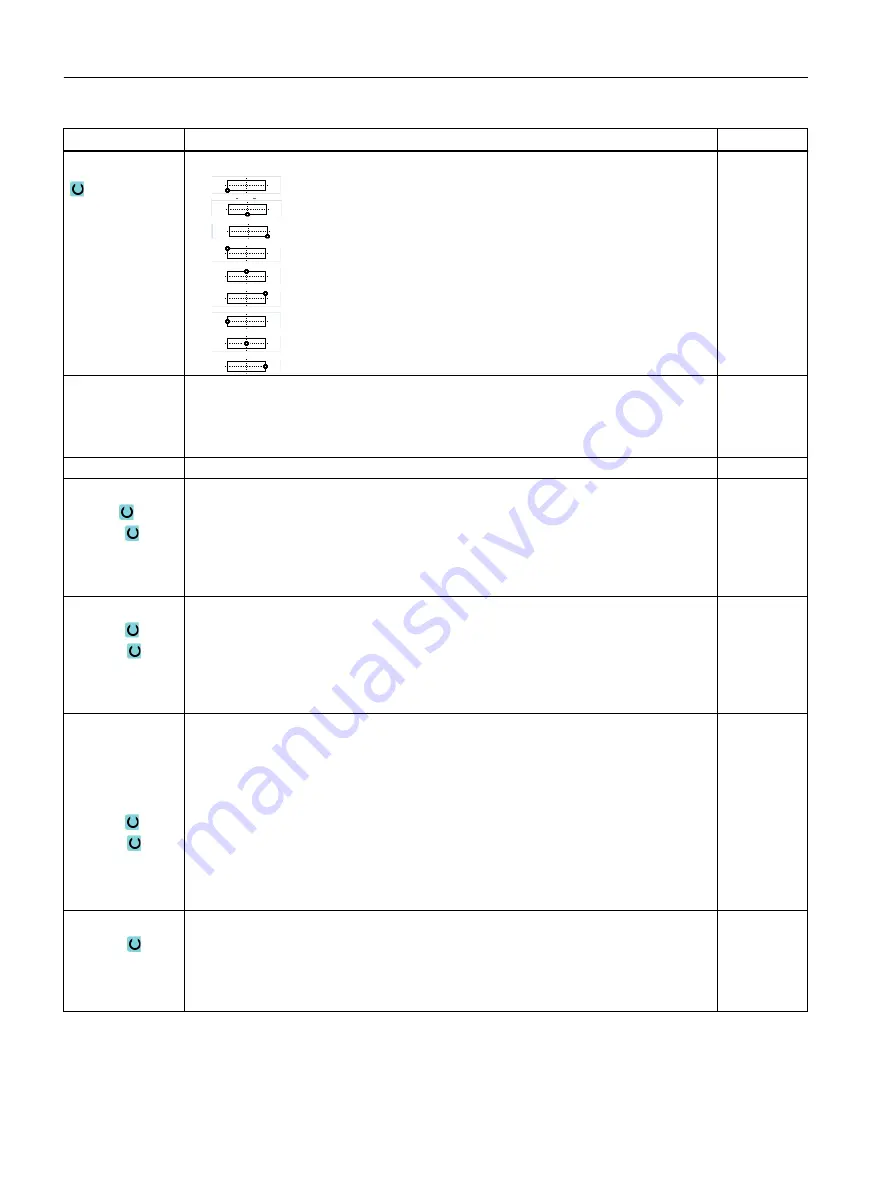
Reference point
Position of the reference point
●
bottom left
●
bottom center
●
bottom right
●
top left
●
top center
●
top right
●
left-hand edge
●
center
●
right-hand edge
Mirror writing
● Yes
The mirrored text is engraved on the workpiece.
● No
The text is engraved on the workpiece without mirroring.
Engraving text
maximum 100 characters
X0 or R
Y0 or α0
Z0
(only for G code)
The positions refer to the reference point:
Reference point X or reference point length polar
Reference point Y or reference point angle polar
Reference point Z
mm
mm or de‐
grees
mm
X0 or L0
Y0 or C0
Z0
(only ShopTurn)
Face C: The positions refer to the reference point:
Reference point X or reference point length polar
Reference point Y or reference point angle polar
Reference point Z
mm
mm or de‐
grees
mm
CP
X0 or L0
Y0 or C0
Z0
(only ShopTurn)
Face Y: The positions refer to the reference point:
Positioning angle for machining area
Angle CP does not have any effect on the machining position in relation to the workpiece.
It is only used to position the workpiece with the rotary axis C in such a way that machining
is possible on the machine.
Reference point X or reference point length polar
Reference point Y or reference point polar angle
Reference point Z
Degrees
mm
mm or de‐
grees
mm
Y0 or C0
Z0
X0
(only ShopTurn)
Peripheral surface C: The positions refer to the reference point:
Reference point Y or reference point angle polar – (only for single position)
Reference point Z
Cylinder diameter ∅
mm or de‐
grees
mm
mm
Programming technology functions (cycles)
10.4 Milling
Turning
562
Operating Manual, 06/2019, A5E44903486B AB


