


Date Code 20010625
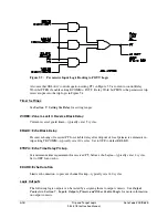
Trip and Target Logic
5-15
SEL-311L Instruction Manual
Enable Setting ECOMM
The POTT, PUTT, DCUB, and DCB tripping schemes are enabled with enable setting ECOMM.
Setting choices are:
ECOMM = N
(no communications-assisted trip scheme enabled)
ECOMM = POTT
(POTT or PUTT scheme)
ECOMM = DCUB1
(DCUB scheme for two-terminal line [communications from one
remote terminal])
ECOMM = DCUB2
(DCUB scheme for three-terminal line [communications from
two remote terminals])
ECOMM = DCB
(DCB scheme)
These tripping schemes can all work in two-terminal or three-terminal line applications. The
DCUB scheme requires separate settings choices for these applications (ECOMM = DCUB1 or
DCUB2) because of unique DCUB logic considerations.
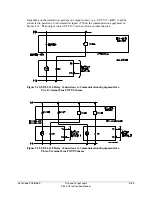
In most cases, these tripping schemes require Zone/Level 3 elements set direction reverse
(setting DIR3 = R); see Figure 5.6. Note that Zone 1 and Zone 2 are fixed in the forward
direction.
See
Directional Control Settings
, in
Section 4: Loss-of-Potential, CCVT Transient Detection,
Load-Encroachment, and Directional Element Logic
for more information on Zone/Level
direction settings DIR3 and DIR4.
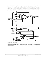
POTT, PUTT, DCUB, and DCB communications-assisted tripping schemes are explained in
subsections that follow.
Use M
IRRORED
B
ITS
communications to implement any of these tripping schemes efficiently
and economically. M
IRRORED
B
ITS
technology is generally used with either POTT or DCUB
tripping schemes. If the communications channel is reliable and noise-free, e.g. dark fiber, then
POTT gives unsurpassed security and very good dependability. If the communications channel
is less than perfect, but communications channel failures are not likely to be coincident with
external faults, then DCUB gives a very good combination of security and dependability.
Trip Setting TRCOMM
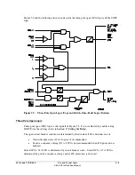
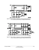
The POTT, PUTT, DCUB, and DCB tripping schemes use SEL
OGIC
control equation trip setting
TRCOMM for those tripping elements that are supervised by the communications-assisted trip
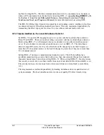
logic (see top half of Figure 5.4). Setting TRCOMM is typically set with Zone 2 overreaching
distance elements (fixed direction forward):
M2P
Zone 2 phase distance instantaneous element
Z2G
Zone 2 ground distance instantaneous element
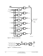
The exception is a DCB scheme, where Zone 2 overreaching distance elements (set direction
forward) with a short delay are used instead. The short delays provide necessary carrier
coordination delays (waiting for the block trip signal). See Figure 5.16. These elements are
entered in trip setting TRCOMM.
Summary of Contents for SEL-311L
Page 6: ......
Page 8: ......
Page 26: ......
Page 54: ......
Page 144: ......
Page 216: ......
Page 252: ......
Page 302: ......
Page 338: ......
Page 480: ......
Page 484: ......
Page 486: ......
Page 502: ......
Page 532: ...12 28 Standard Event Reports and SER Date Code 20010625 SEL 311L Instruction Manual 4 ...
Page 552: ......
Page 554: ......
Page 574: ......
Page 576: ......
Page 596: ......
Page 602: ......
Page 628: ......
Page 656: ......
Page 662: ......
Page 664: ......
Page 688: ......
Page 700: ......
Page 716: ......
Page 722: ......
Page 734: ......