


13-4
Testing, Troubleshooting, and Commissioning
Date Code 20010625
SEL-311L Instruction Manual
TARGET
Command
Use the TARGET (
TAR
) command to view the state of relay control inputs,
relay outputs, and relay elements individually during a test. The TARGET
command is available at the serial ports and the front panel. See
Section 10:
Line Current Differential Communications and Serial Port
Communications and Commands
and
Section 11: Front-Panel Interface.
PULSE
Command
Use the PULSE (
PUL
) command to test the contact output circuits. The
PULSE command is available at the serial ports and the front panel. See
Section 10: Line Current Differential Communications and Serial Port
Communications and Commands
.
Low-Level Test Interface
The SEL-311L Relay has a low-level test interface between the calibrated input module and the
separately calibrated processing module. You may test the relay in either of two ways: by using
secondary injection testing or by applying low magnitude ac voltage signals to the low-level test
interface. Access the test interface by removing the relay front panel.
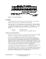
Figure 13.1 shows the low-level interface connections. This drawing also appears on the inside
of the relay front panel. Remove the ribbon cable between the two modules to access the outputs
of the input module and the inputs to the processing module (relay main board).
You can test the relay processing module using signals from the SEL-RTS Low-Level Relay
Test System. Never apply voltage signals greater than 9 volts peak-peak to the low-level test
interface. Figure 13.1 shows the signal scaling factors.
CAUTION
!
The relay contains devices sensitive to Electrostatic Discharge (ESD).
When working on the relay with front or top cover removed, work
surfaces and personnel must be properly grounded or equipment
damage may result.
You can test the input module two different ways:
1. Measure the outputs from the input module with an accurate voltmeter (measure signal
pin to GND pin), and compare the readings to accurate instruments in the relay input
circuits, or
2. Replace the ribbon cable, press the front-panel
{METER}
button, and compare the
relay readings to other accurate instruments in the relay input circuits.
Summary of Contents for SEL-311L
Page 6: ......
Page 8: ......
Page 26: ......
Page 54: ......
Page 144: ......
Page 216: ......
Page 252: ......
Page 302: ......
Page 338: ......
Page 480: ......
Page 484: ......
Page 486: ......
Page 502: ......
Page 532: ...12 28 Standard Event Reports and SER Date Code 20010625 SEL 311L Instruction Manual 4 ...
Page 552: ......
Page 554: ......
Page 574: ......
Page 576: ......
Page 596: ......
Page 602: ......
Page 628: ......
Page 656: ......
Page 662: ......
Page 664: ......
Page 688: ......
Page 700: ......
Page 716: ......
Page 722: ......
Page 734: ......