


3-78
Line Current Differential, Distance, Out-of-Step, Overcurrent,
Date Code 20011112
Voltage, Synchronism Check, and Frequency Elements
SEL-311L Instruction Manual
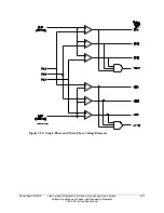
Synchronism Check Elements Voltage Inputs
The two synchronism check elements use voltage inputs V
P
and V
S
for both elements:
V
P
Phase input voltage (V
A
, V
B
, V
C
, V
AB
, V
BC
, or V
CA
), designated by setting SYNCP (e.g.,
if SYNCP = VB, then V
P
= V
B
)
V
S
Synchronism check voltage, from SEL-311L Relay rear-panel voltage input VS
For example, if V
P
is designated as phase input voltage V
B
(setting SYNCP = VB), then
rear-panel voltage input VS is connected to B-phase on the other side of the circuit breaker. The
voltage across terminals VB-N is synchronism checked with the voltage across terminals VS-NS
(see Figure 1.4 and Figures 2.11 and 2.12).
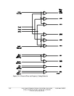
System Frequencies Determined from Voltages V
A
and V
S
To determine slip frequency, you need to determine the system frequencies on both sides of the
circuit breaker. Voltage V
S
determines the frequency on one side. Voltage V
A
determines the
frequency on the other side.
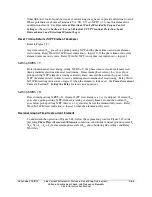
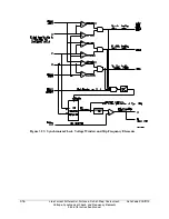
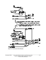
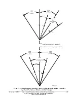
Synchronism Check Elements Operation
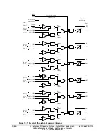
Refer to Figure 3.53 and Figure 3.54.
Voltage Window
Refer to Figure 3.53.
Single-phase voltage inputs V
P
and V
S
are compared to a voltage window, to verify that the
voltages are “healthy” and lie within settable voltage limits 25VLO and 25VHI. If both voltages
are within the voltage window, the following Relay Word bits assert:
59VP indicates that voltage V
P
is within voltage window setting limits 25VLO and 25VHI
59VS indicates that voltage V
S
is within voltage window setting limits 25VLO and 25VHI
As discussed previously, voltage V
A
determines the frequency on the voltage V
P
side of the circuit
breaker. Voltage V
A
is also compared against voltage limits 25VLO and 25VHI to assure
“healthy voltage” for frequency determination, with corresponding Relay Word bit output 59VA.
If V
P
is a phase-to-phase voltage, V
A
is multiplied internally by
√
3 for the 25VLO and 25VHI
checks.
Other Uses for Voltage Window Elements
If voltage limits 25VLO and 25VHI are applicable to other control schemes, Relay Word bits
59VP, 59VS, and 59VA can be used in other logic at the same time they are used in the
synchronism check logic.
If synchronism check is not being used, Relay Word bits 59VP, 59VS, and 59VA can still be
used in other logic, with voltage limit settings 25VLO and 25VHI set as desired. Enable the
synchronism check logic (setting E25 = Y) and make settings 25VLO and 25VHI. Apply Relay
Word bits 59VP, 59VS, and 59VA in the desired logic scheme, using SEL
OGIC
control equations.
Even though synchronism check logic is enabled, the synchronism check logic outputs (Relay
Word bits SF, 25A1, and 25A2) do not need to be used.
Summary of Contents for SEL-311L
Page 6: ......
Page 8: ......
Page 26: ......
Page 54: ......
Page 144: ......
Page 216: ......
Page 252: ......
Page 302: ......
Page 338: ......
Page 480: ......
Page 484: ......
Page 486: ......
Page 502: ......
Page 532: ...12 28 Standard Event Reports and SER Date Code 20010625 SEL 311L Instruction Manual 4 ...
Page 552: ......
Page 554: ......
Page 574: ......
Page 576: ......
Page 596: ......
Page 602: ......
Page 628: ......
Page 656: ......
Page 662: ......
Page 664: ......
Page 688: ......
Page 700: ......
Page 716: ......
Page 722: ......
Page 734: ......