


Date Code 20010625
Installation
2-19
SEL-311L Instruction Manual
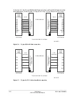
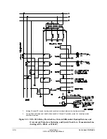
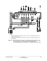
Output Contact Jumpers
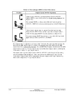
Table 2.3 shows the correspondence between output contact jumpers and the output contacts they
control. The referenced figures show the exact location and correspondence. With a jumper in
the A position, the corresponding output contact is an “a” type output contact. An “a” type
output contact is closed when the associated SEL
OGIC
equation is asserted, and open when the
associated SEL
OGIC
equation is deasserted. With a jumper in the B position, the corresponding
output contact is a “b” type output contact. A “b” type output contact is closed when the
associated SEL
OGIC
equation is deasserted, and open when the associated SEL
OGIC
equation is
asserted. These jumpers are soldered in place.
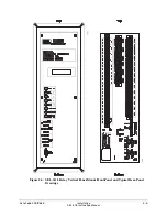
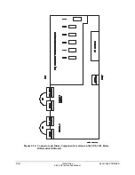
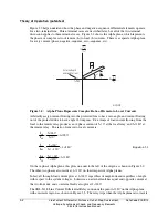
In Figure 2.13, note that the ALARM output contact is a “b” type output contact and the other
output contacts are all “a” type output contacts. This is how these jumpers are configured in a
standard relay shipment. Refer to Figure 7.26 and Figure 7.27 for examples of output contact
operation for different output contact types.
The fast, high-current interrupting contacts OUT201–OUT206 are all “a” type contacts and
cannot be configured as “b” type contacts.
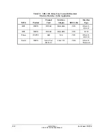
Table 2.3: Output Contact Jumpers and Corresponding Output Contacts
SEL-311L Relay
Model Number
Output Contact
Jumpers
Corresponding
Output Contacts
Reference
Figure
All Models
JMP21–JMP29 (but not JMP23)
ALARM–OUT101
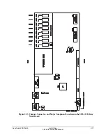
“Extra Alarm” Output Contact Control Jumper
All the SEL
311L Relays have a dedicated alarm output contact labeled ALARM (see Figure 2.2
through Figure 2.5). Often more than one alarm output contact is needed for such applications as
local or remote annunciation, backup schemes, etc.
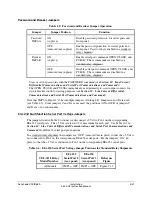
Convert the output contact adjacent to the dedicated ALARM output contact to operate as an
“extra alarm” output contact by moving jumper JMP23 on the main board (see Table 2.4).
With the jumper in one position, the output contact operates regularly. With the jumper in the
other position, the output contact is driven by the same signal that operates the dedicated
ALARM output contact (see Table 2.4).
Do not convert OUT107 to an “extra alarm” if it is used as a line current differential hardware
alarm. When configured as an “extra alarm,” OUT107 no longer responds to SEL
OGIC
control
equation OUT107 = 87HWAL.
Summary of Contents for SEL-311L
Page 6: ......
Page 8: ......
Page 26: ......
Page 54: ......
Page 144: ......
Page 216: ......
Page 252: ......
Page 302: ......
Page 338: ......
Page 480: ......
Page 484: ......
Page 486: ......
Page 502: ......
Page 532: ...12 28 Standard Event Reports and SER Date Code 20010625 SEL 311L Instruction Manual 4 ...
Page 552: ......
Page 554: ......
Page 574: ......
Page 576: ......
Page 596: ......
Page 602: ......
Page 628: ......
Page 656: ......
Page 662: ......
Page 664: ......
Page 688: ......
Page 700: ......
Page 716: ......
Page 722: ......
Page 734: ......