


3-4
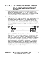
Line Current Differential, Distance, Out-of-Step, Overcurrent,
Date Code 20011112
Voltage, Synchronism Check, and Frequency Elements
SEL-311L Instruction Manual
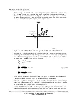
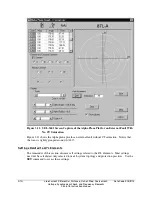
Set Phase Differential Elements 87LA, 87LB, and 87LC to Detect Internal Three-Phase
Faults.
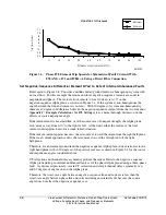
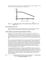
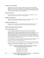
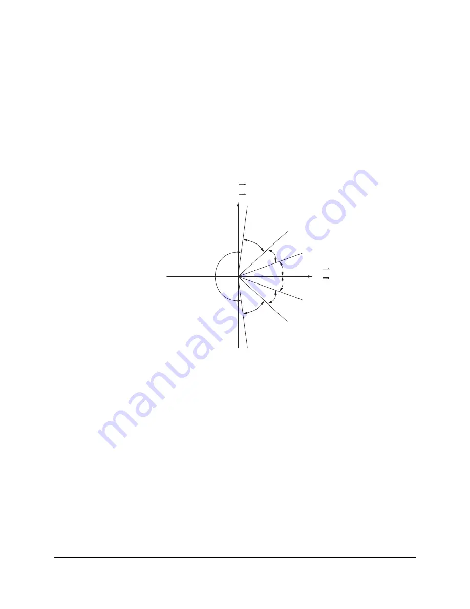
Refer to Figure 3.4. Consider a three-phase fault at midline on a homogenous system with no
load flow. For this example, the remote and local currents are equal in magnitude and phase.
The vector ratio of remote to local currents is 1
∠
0°. This plots one unit to the right of the origin,
as shown in Figure 3.4. If the system is non-homogenous then the line-end current angles differ,
and hence the angle of the current ratio is not zero. If the source impedance angles differ by 10
degrees, and there is an angular difference of 10 degrees between the sources, then the angle
between remote and local currents can approach 20 degrees.
Appendix J: Example Calculations
for 87L Settings
gives a more thorough discussion of the effects of source angle and source
impedance angle.
M311L078
Re
I
R
I
L
( (
Im
1
∠
0˚
I
R
I
L
( (
87LANG = 195˚
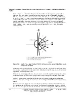
A: 20˚ shift caused by source angle and source impedance angle.
B: 21.6˚ shift caused by 2 ms channel assymetry.
C: 40˚ shift caused by CT saturation.
A
A
B
B
C
C
Figure 3.4: Alpha Plane Angel Setting 87LANG Is Based on Maximum Alpha Plane Angle
for an External Fault
If the internal fault is not at midline, or if the sources do not have equal strength, the Alpha plane
ratio moves away from 1
∠
0° to the right or left. In the limit, either the remote or the local current
approaches zero during weak-infeed.
If the remote current approaches zero, the ratio moves toward the origin from the right half-plane.
If the local current approaches zero, the ratio moves toward far right end of the right half-plane.
Therefore, for an internal three-phase fault the phase current ratio lies in the right hand plane
/-20 degrees of the positive real axis as shown in Figure 3.4 for the source and impedance
angles.
Now consider a data alignment error caused by unequal delays in transmit and receive channels.
In a unidirectional SONET ring with 20 nodes, the transmit and receive times might be different
by 2 ms, assuming adjacent nodes in one direction and 19 intervening nodes in the other direction
Summary of Contents for SEL-311L
Page 6: ......
Page 8: ......
Page 26: ......
Page 54: ......
Page 144: ......
Page 216: ......
Page 252: ......
Page 302: ......
Page 338: ......
Page 480: ......
Page 484: ......
Page 486: ......
Page 502: ......
Page 532: ...12 28 Standard Event Reports and SER Date Code 20010625 SEL 311L Instruction Manual 4 ...
Page 552: ......
Page 554: ......
Page 574: ......
Page 576: ......
Page 596: ......
Page 602: ......
Page 628: ......
Page 656: ......
Page 662: ......
Page 664: ......
Page 688: ......
Page 700: ......
Page 716: ......
Page 722: ......
Page 734: ......