


3-36
Line Current Differential, Distance, Out-of-Step, Overcurrent,
Date Code 20011112
Voltage, Synchronism Check, and Frequency Elements
SEL-311L Instruction Manual
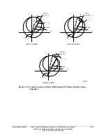
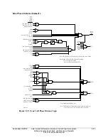
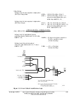
compensator distance element measures impedance through the transformer for all
phase faults and will not overreach on ground faults. See
Application Guide
AG96-16:
Applying SEL Distance Relays on Lines with Power Transformers or
Open Delta VTs
for more information.
•
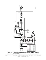
Blocking reclose on three-phase faults. Relay Word bits MPP
n
(Zone/Level
n
phase-
to-phase compensator distance element) and MABC
n
(Zone/Level
n
three-phase
compensator distance element) may be used to discriminate between phase-to-phase
and three-phase faults in the SEL
OGIC
control equation 79DTL (drive-to-lockout).
79DTL = MABC2 * !MPP2 …
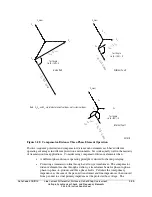
Note that both three-phase and single-phase compensator-distance elements will
operate for
Phase A-B faults within the protected zone since the three-phase element
uses V
C
mem (V
C
memorized voltage) for polarizing.
Compensator distance and positive-sequence polarized distance may not be applied at the same
time. Select compensator distance with a “C” suffix to the number of zones in the E21P setting
(e.g., 3C is three zones of compensator distance relaying). If EADVS = N and compensator
distance elements are selected, E21MG is set to “N” and hidden. If EADVS = Y, setting E21MG
is visible and the user may apply ground distance relaying along with compensator distance phase
relaying.
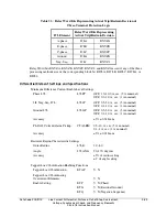
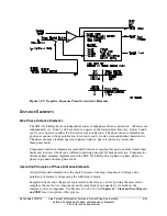
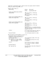
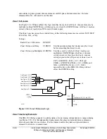
Mho Phase Distance Elements (Zones 1–4)
Enable Setting:
E21P
Setting range for Mho Phase Distance
Elements (Z1P through Z4P):
OFF, 0.05 to 64
Ω
sec, 0.01
Ω
steps (5 A nominal)
OFF, 0.25 to 320
Ω
sec, 0.01
Ω
steps
(1 A nominal)
Minimum sensitivity is controlled by the pickup of
the supervising phase-to-phase overcurrent
elements for each zone.
Accuracy:
±
5% of setting at line angle for 30
≤
SIR
≤
60
±
3% of setting at line angle for SIR < 30
Transient Overreach:
< 5% of setting plus steady state accuracy
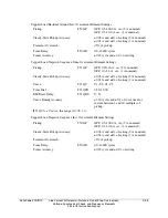
Phase-to-Phase Current Fault Detectors (Zones 1–4)
Setting Range for Phase-to-Phase Current
Fault Detectors (50PP1–50PP4):
Note:
If setting EADVS = N, settings
50PP2–50PP4 are at minimum
values and are hidden.
0.50–170.00 A
P-P
secondary, 0.01 A steps
(5 A nominal)
0.10–34.00 A
P-P
secondary, 0.01 A steps
(1 A nominal)
Accuracy:
±
0.05 A and ±3% of setting (5 A nominal)
±
0.01 A and ±3% of setting (1 A nominal)
Transient Overreach:
< 5% of pickup
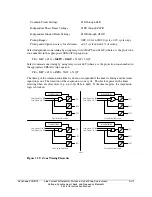
Max. Operating Time:
See pickup and reset time curves in Figure 3.43
and Figure 3.44.
Summary of Contents for SEL-311L
Page 6: ......
Page 8: ......
Page 26: ......
Page 54: ......
Page 144: ......
Page 216: ......
Page 252: ......
Page 302: ......
Page 338: ......
Page 480: ......
Page 484: ......
Page 486: ......
Page 502: ......
Page 532: ...12 28 Standard Event Reports and SER Date Code 20010625 SEL 311L Instruction Manual 4 ...
Page 552: ......
Page 554: ......
Page 574: ......
Page 576: ......
Page 596: ......
Page 602: ......
Page 628: ......
Page 656: ......
Page 662: ......
Page 664: ......
Page 688: ......
Page 700: ......
Page 716: ......
Page 722: ......
Page 734: ......