

10-4
Line Current Differential Communications
Date Code 20010625
and Serial Port Communications and Commands
SEL-311L Instruction Manual
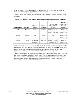
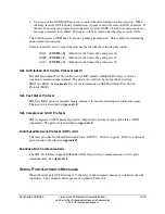
SEL-311L
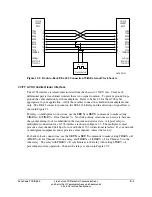
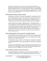
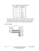
CHX/CHY
DB-25
TXDA
2
TXDB
14
RXDA
3
RXDB
16
Settings:
TIMRX=E
SEL-311L
CHX/CHY
DB-25
2
TXDA
14
TXDB
3
RXDA
16
RXDB
Settings:
TIMRX=I
DWG: M311L083
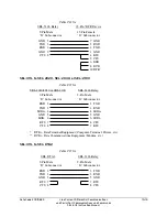
Figure 10.2: Back-to-Back CCITT G.703 Connection
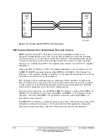
IEEE Proposed Standard PC37.94 Multimode Fiber Optic Interface
IEEE Proposed Standard PC37.94 defines a direct relay-to-multiplexer interface over
inexpensive multimode fiber-optic cable. This prevents problems associated with grounding
electrical interfaces. It also provides excellent noise immunity. The Standard defines the data
structure and encoding, and also defines the physical interface (connectors, light wavelength,
fiber type, etc.) ensuring that all PC37.94 compliant relays interface with all PC37.94 compliant
multiplexers.
Connect the SEL-311L Relay to a PC37.94 compliant multiplexer as shown in Figure 2.8. Use
the
SET X
or
SET Y
commands to make setting TIMRX = E (TIMRY = E for Channel Y) in
both relays. This configures the SEL-311L Relay to synchronize the transmit date rate to exactly
match the receive data rate set by the multiplexer.
PC37.94 defines several troubleshooting aids, including a Yellow Alarm bit. At present, the
SEL-311L Relay does not report the status of the receive Yellow Alarm bit, nor does it generate
a Yellow Alarm bit. Consult the documentation provided with your multiplexer to determine
when and if the multiplexer asserts the Yellow Alarm indicators.
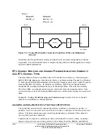
For back-to-back connections, use the
SET X
or
SET Y
commands to make setting TIMRX = E
(TIMRY = E for Channel Y) in one relay, and TIMRX = I (TIMRY = I for Channel Y) in the
other relay. The relay with TIMRY = E synchronizes to the relay with setting TIMRY = I,
providing error free operation.
The IEEE-PC37.94 interface is suitable for distances up to 2 km, either between the relay and the
multiplexer or directly between relays. For longer haul direct-fiber applications using either
multimode or single-mode fiber, order the 1300 nm fiber-optic interface described next.
Summary of Contents for SEL-311L
Page 6: ......
Page 8: ......
Page 26: ......
Page 54: ......
Page 144: ......
Page 216: ......
Page 252: ......
Page 302: ......
Page 338: ......
Page 480: ......
Page 484: ......
Page 486: ......
Page 502: ......
Page 532: ...12 28 Standard Event Reports and SER Date Code 20010625 SEL 311L Instruction Manual 4 ...
Page 552: ......
Page 554: ......
Page 574: ......
Page 576: ......
Page 596: ......
Page 602: ......
Page 628: ......
Page 656: ......
Page 662: ......
Page 664: ......
Page 688: ......
Page 700: ......
Page 716: ......
Page 722: ......
Page 734: ......