


Date Code 20010625
Inputs, Outputs, Timers, and Other Control Logic
7-23
SEL-311L Instruction Manual
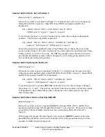
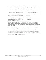
Table 7.5: SEL
OGIC
Control Equation Settings for Switching Active Setting Group
Between Setting Groups 1 and 4
Setting Group 1
Setting Group 4
SV8 = SG1
SV8 = SG4
SS1 = 0
SS1 = IN105 * SV8T
SS2 = 0
SS2 = 0
SS3 = 0
SS3 = 0
SS4 = IN105 * SV8T
SS4 = 0
SS5 = 0
SS5 = 0
SS6 = 0
SS6 = 0
SEL
OGIC
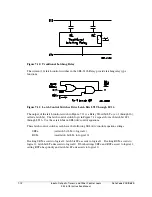
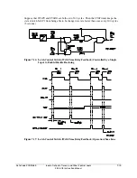
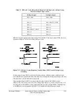
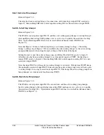
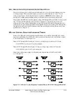
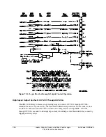
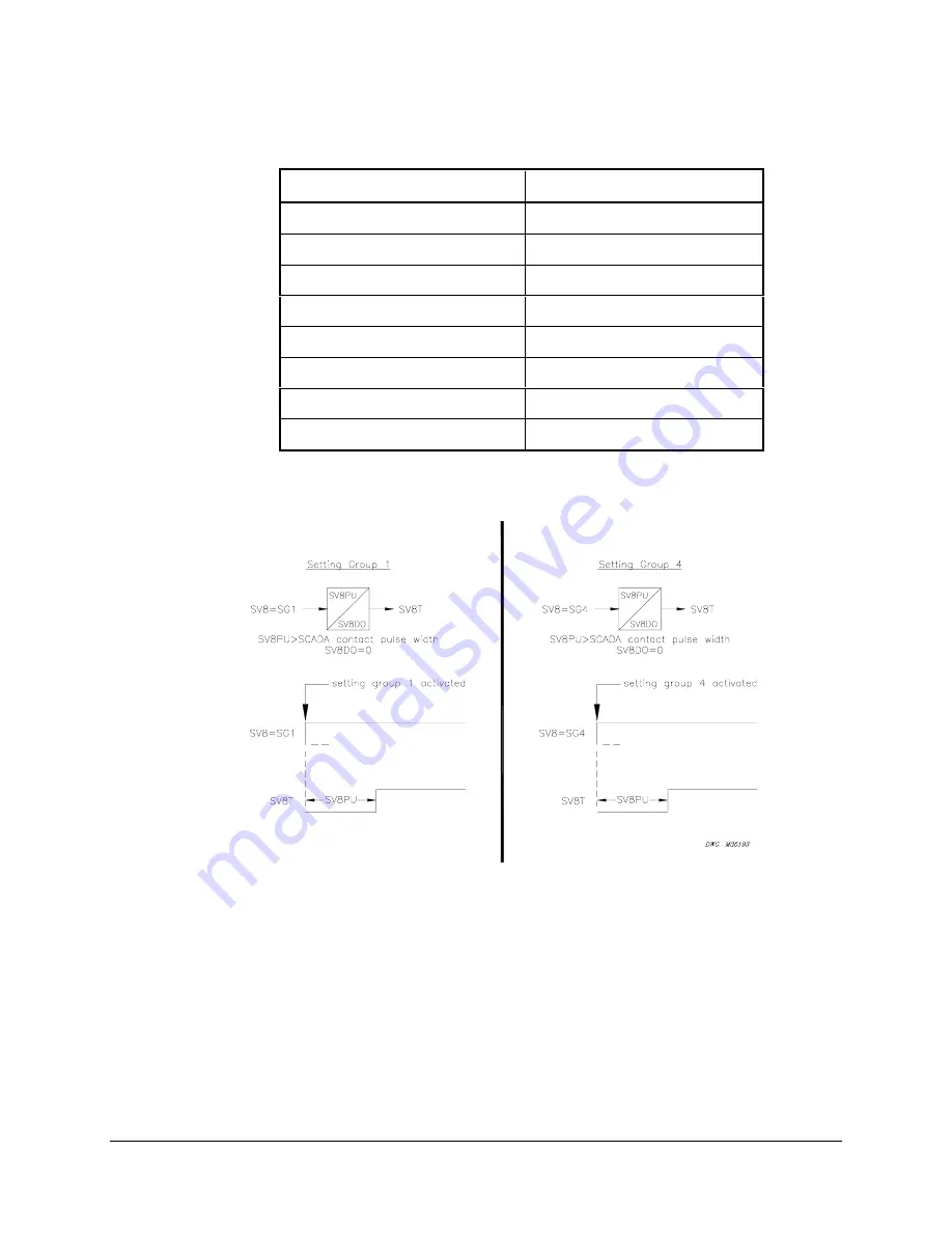
control equation timer input setting SV8 in Table 7.5 has logic output SV8T, shown in
operation in Figure 7.19 for both setting Groups 1 and 4.
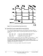
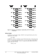
Figure 7.19: SEL
OGIC
Control Equation Variable Timer SV8T Used in Setting Group
Switching
In this example, timer SV8T is used in both setting groups—different timers could have been
used with the same operational result. The timers reset during the setting group change, allowing
the same timer to be used in both setting groups.
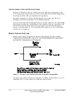
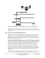
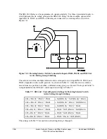
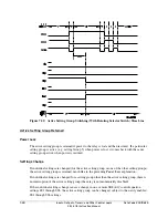
Timer pickup setting SV8PU is set greater than the pulse width of the SCADA contact
(Figure 7.18). This allows only one active setting group change (e.g., from setting Group 1 to 4)
for each pulse of the SCADA contact (and subsequent assertion of input IN105). The functions
of the SEL
OGIC
control equations in Table 7.5 are explained in the following example.
Summary of Contents for SEL-311L
Page 6: ......
Page 8: ......
Page 26: ......
Page 54: ......
Page 144: ......
Page 216: ......
Page 252: ......
Page 302: ......
Page 338: ......
Page 480: ......
Page 484: ......
Page 486: ......
Page 502: ......
Page 532: ...12 28 Standard Event Reports and SER Date Code 20010625 SEL 311L Instruction Manual 4 ...
Page 552: ......
Page 554: ......
Page 574: ......
Page 576: ......
Page 596: ......
Page 602: ......
Page 628: ......
Page 656: ......
Page 662: ......
Page 664: ......
Page 688: ......
Page 700: ......
Page 716: ......
Page 722: ......
Page 734: ......