


Date Code 20010625
Close and Reclose Logic
6-21
SEL-311L Instruction Manual
Setting 79RIS = logical 1 at all times. Any time a logical 0 to logical 1 transition is detected
by setting 79RI, open interval timing will be initiated (unless prevented by other means).
3. If the following setting is made:
79RI = 0
(numeral
0)
reclosing will never take place (reclosing is never initiated). The reclosing relay is effectively
inoperative.
4. If the following setting is made:
79RIS = 0
(numeral 0)
reclosing will never take place (the reclosing relay goes directly to the lockout state any time
reclosing is initiated). The reclosing relay is effectively inoperative.
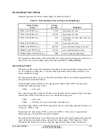
Drive-to-Lockout and Drive-to-Last Shot Settings (79DTL and 79DLS, Respectively)
When 79DTL = logical 1, the reclosing relay goes to the Lockout State (Relay Word bit 79LO =
logical 1), and the front
-
panel LO (Lockout) LED illuminates.
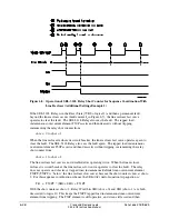
79DTL has a 60-cycle dropout time. This keeps the drive-to-lockout condition up 60 more
cycles after 79DTL has reverted back to 79DTL = logical 0. This is useful for situations where
both of the following are true:
•
Any of the trip and drive-to-lockout conditions are “pulsed” conditions (e.g., the
OPE
command Relay Word bit, OC, asserts for only 1/4 cycle—refer to the following
Settings Example
).
•
Reclose initiation is by the breaker contact opening (e.g., 79RI = !52A—refer to
Additional Settings Example
in the preceding setting 79RI [reclose initiation]
discussion).
Then the drive-to-lockout condition overlaps reclose initiation and the SEL-311L Relay stays in
lockout after the breaker trips open.
When 79DLS = logical 1, the reclosing relay goes to the last shot, if the shot counter is not at a
shot value greater than or equal to the calculated last shot (see
Reclosing Relay Shot Counter
earlier in this subsection).
Settings Example
The drive-to-lockout example setting is:
79DTL = !IN102 + LB3 + OC
Optoisolated input IN102 is set to operate as a reclose enable switch (see
Optoisolated Inputs
in
Section 7: Inputs, Outputs, Timers, and Other Control Logic
). When Relay Word bit IN102 =
logical 1 (reclosing enabled), the relay is not driven to the Lockout State (assuming local bit LB3
= logical 0, too):
!IN102
= !(logical 1) = NOT(logical 1) = logical 0
79DTL
= !IN102 + LB3 + OC = (logical 0) + LB3 = LB3 + OC
Summary of Contents for SEL-311L
Page 6: ......
Page 8: ......
Page 26: ......
Page 54: ......
Page 144: ......
Page 216: ......
Page 252: ......
Page 302: ......
Page 338: ......
Page 480: ......
Page 484: ......
Page 486: ......
Page 502: ......
Page 532: ...12 28 Standard Event Reports and SER Date Code 20010625 SEL 311L Instruction Manual 4 ...
Page 552: ......
Page 554: ......
Page 574: ......
Page 576: ......
Page 596: ......
Page 602: ......
Page 628: ......
Page 656: ......
Page 662: ......
Page 664: ......
Page 688: ......
Page 700: ......
Page 716: ......
Page 722: ......
Page 734: ......