

Date Code 20010625
Inputs, Outputs, Timers, and Other Control Logic
7-27
SEL-311L Instruction Manual
Selector Switch Starts Out in Position 3
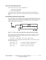
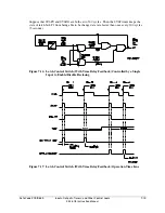
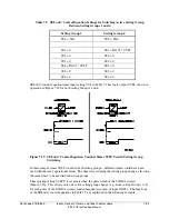
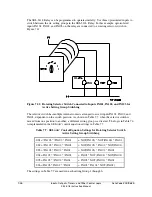
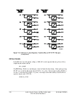
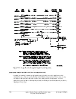
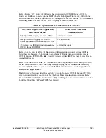
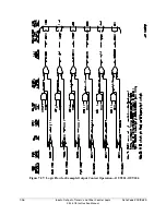
Refer to Table 7.7 and Figure 7.22.
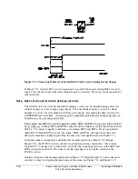
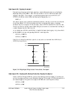
If the selector switch is in position 3 in Figure 7.21, setting Group 3 is the active setting group
(Relay Word bit SG3 = logical 1). Inputs IN101 and IN102 are energized and IN103 is
deenergized:
SS3 = !IN103 * IN102 * IN101 = NOT(IN103) * IN102 * IN101
= NOT(logical 0) * logical 1 * logical 1 = logical 1
To get from the position 3 to position 5 on the selector switch, the switch passes through the
position 4. The switch is only briefly in position 4:
SS4 = IN103 * !IN102 * !IN101 = IN103 * NOT(IN102) * NOT(IN101)
= logical 1 * NOT(logical 0) * NOT(logical 0) = logical 1
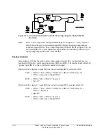
but not long enough to be qualified by time setting TGR in order to change the active setting
group to setting Group 4. For such a rotating selector switch application, qualifying time setting
TGR is typically set at 180 to 300 cycles. Set TGR long enough to allow the selector switch to
pass through intermediate positions without changing the active setting group, until the switch
rests on the desired setting group position.
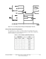
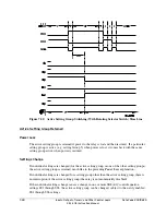
Selector Switch Switched to Position 5
Refer to Figure 7.22.
If the selector switch is rested on position 5 in Figure 7.21, setting Group 5 becomes the active
setting group (after qualifying time setting TGR; Relay Word bit SG5 = logical 1). Inputs IN101
and IN103 are energized and IN102 is deenergized:
SS5 = IN103 * !IN102 * IN101 = IN103 * NOT(IN102) * IN101
= logical 1 * NOT(logical 0) * logical 1 = logical 1
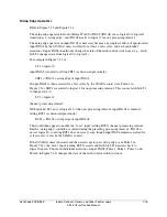
To get from position 5 to position REMOTE on the selector switch, the switch passes through
the positions 4, 3, 2, and 1. The switch is only briefly in the these positions, but not long enough
to be qualified by time setting TGR in order to change the active setting group to any one of
these setting groups.
Selector Switch Now Rests on Position REMOTE
If the selector switch is rested on position REMOTE, all inputs IN101, IN102, and IN103 are
deenergized and all settings SS1 through SS6 in Table 7.7 are at logical 0. The last active setting
group (Group 5 in this example) remains the active setting group (Relay Word bit SG5 =
logical 1).
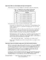
With settings SS1 through SS6 all at logical 0, the serial port
GROUP
command or the front-
panel GROUP pushbutton can be used to switch the active setting group from Group 5, in this
example, to another desired setting group.
Summary of Contents for SEL-311L
Page 6: ......
Page 8: ......
Page 26: ......
Page 54: ......
Page 144: ......
Page 216: ......
Page 252: ......
Page 302: ......
Page 338: ......
Page 480: ......
Page 484: ......
Page 486: ......
Page 502: ......
Page 532: ...12 28 Standard Event Reports and SER Date Code 20010625 SEL 311L Instruction Manual 4 ...
Page 552: ......
Page 554: ......
Page 574: ......
Page 576: ......
Page 596: ......
Page 602: ......
Page 628: ......
Page 656: ......
Page 662: ......
Page 664: ......
Page 688: ......
Page 700: ......
Page 716: ......
Page 722: ......
Page 734: ......