


3-52
Line Current Differential, Distance, Out-of-Step, Overcurrent,
Date Code 20011112
Voltage, Synchronism Check, and Frequency Elements
SEL-311L Instruction Manual
O
VERCURRENT
P
ROTECTION
The SEL-311L Relay provides the following overcurrent protection elements:
•
Phase instantaneous/definite-time overcurrent elements
•
Residual ground instantaneous/definite-time overcurrent elements
•
Negative-sequence instantaneous/definite-time overcurrent elements
•
Phase inverse time overcurrent elements
•
Residual ground inverse time overcurrent elements
•
Negative-sequence inverse time overcurrent elements
All of the elements listed above are either directional or nondirectional, if potentials are present at
terminals VA, VB, and VC. If you apply the SEL-311L as a line current differential relay with
no potentials applied, directional control is available only to residual ground elements when
ORDER = I and polarizing current (IP) is available. Under tapped-load conditions the differential
function can also provide directional control for the tapped-load coordination elements.
SEL
OGIC
torque control equations also control the operation of various levels of overcurrent
elements. For example, with application setting 87L, the factory default torque control 67P1TC
is set such that the Level 1 phase instantaneous/definite-time element is enabled only if the line
current differential protection is not available (possibly due to channel loss). Configure the
torque control equations for each of the overcurrent elements to suite your application needs.
Refer to
Section 14: Application Settings for SEL-311L Relays
for more details.
For more information about SEL
OGIC
control equations refer to
Section 7: Inputs, Outputs,
Timers and Other Control Logic
.
For directional element logic refer to
Section 4: Loss-of-Potential, CCVT Transient Detection,
Load-Encroachment, and Directional Element Logic
.
I
NSTANTANEOUS
/D
EFINITE
-T
IME
O
VERCURRENT
E
LEMENTS
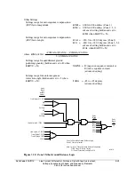
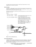
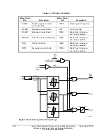
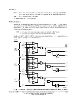
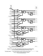
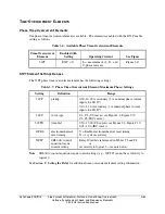
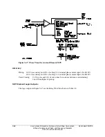
Phase Instantaneous/Definite-Time Overcurrent Elements
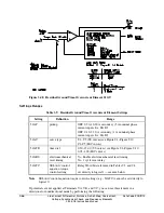
Three levels of phase instantaneous/definite-time overcurrent elements are available. The
different levels are enabled with the E50P enable setting, as shown in Figure 3.42.
All phase instantaneous/definite-time overcurrent elements are available for use in any
user-defined tripping or control scheme.
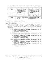
Settings Ranges
Settings range for pickup settings 50P1P through 50P3P:
OFF, 0.25–100.00 A secondary
(5 A nominal phase current inputs, IA, IB, IC)
OFF, 0.05–20.00 A secondary
(1 A nominal phase current inputs, IA, IB, IC)
Settings range for definite-time settings 67P1D through 67P3D:
0.00–16000.00 cycles, in 0.25-cycle steps
Summary of Contents for SEL-311L
Page 6: ......
Page 8: ......
Page 26: ......
Page 54: ......
Page 144: ......
Page 216: ......
Page 252: ......
Page 302: ......
Page 338: ......
Page 480: ......
Page 484: ......
Page 486: ......
Page 502: ......
Page 532: ...12 28 Standard Event Reports and SER Date Code 20010625 SEL 311L Instruction Manual 4 ...
Page 552: ......
Page 554: ......
Page 574: ......
Page 576: ......
Page 596: ......
Page 602: ......
Page 628: ......
Page 656: ......
Page 662: ......
Page 664: ......
Page 688: ......
Page 700: ......
Page 716: ......
Page 722: ......
Page 734: ......