Date Code 20010625
Inputs, Outputs, Timers, and Other Control Logic
7-43
SEL-311L Instruction Manual
Traditional Indicating Panel Lights
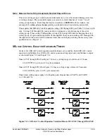
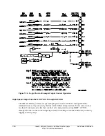
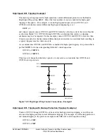
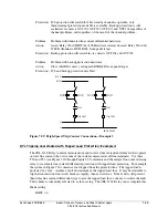
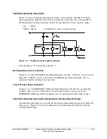
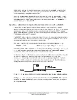
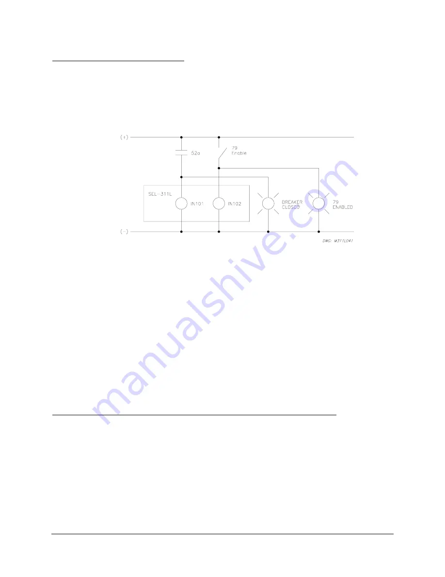
Figure 7.31 shows traditional indicating panel lights wired in parallel with SEL-311L Relay
optoisolated inputs. Input IN101 provides circuit breaker status to the relay, and input IN102
enables/disables reclosing in the relay via the following SEL
OGIC
control equation settings:
52A =
IN101
79DTL = !IN102
[= NOT(IN102); drive-to-lockout setting]
Figure 7.31: Traditional Panel Light Installations
Note that Figure 7.31 corresponds to Figure 7.2.
Reclosing Relay Status Indication
In Figure 7.31, the 79 ENABLED panel light illuminates when the “79 Enable” switch is closed.
When the “79 Enable” switch is open, the 79 ENABLED panel light extinguishes, and it is
understood that the reclosing relay is disabled.
Circuit Breaker Status Indication
In Figure 7.31, the BREAKER CLOSED panel light illuminates when the 52a circuit breaker
auxiliary contact is closed. When the 52a circuit breaker auxiliary contact is open, the
BREAKER CLOSED panel light extinguishes, and it is understood that the breaker is open.
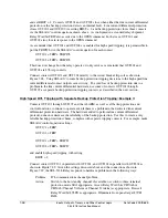
Traditional Indicating Panel Lights Replaced with Rotating Default Display
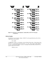
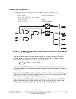
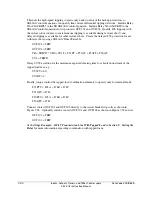
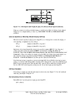
The indicating panel lights are not needed if the rotating default display feature in the SEL-311L
Relay is used. Figure 7.32 shows the elimination of the indicating panel lights by using the
rotating default display.
Summary of Contents for SEL-311L
Page 6: ......
Page 8: ......
Page 26: ......
Page 54: ......
Page 144: ......
Page 216: ......
Page 252: ......
Page 302: ......
Page 338: ......
Page 480: ......
Page 484: ......
Page 486: ......
Page 502: ......
Page 532: ...12 28 Standard Event Reports and SER Date Code 20010625 SEL 311L Instruction Manual 4 ...
Page 552: ......
Page 554: ......
Page 574: ......
Page 576: ......
Page 596: ......
Page 602: ......
Page 628: ......
Page 656: ......
Page 662: ......
Page 664: ......
Page 688: ......
Page 700: ......
Page 716: ......
Page 722: ......
Page 734: ......

