


Date Code 20011112
Line Current Differential, Distance, Out-of-Step, Overcurrent,
3-65
Voltage, Synchronism Check, and Frequency Elements
SEL-311L Instruction Manual
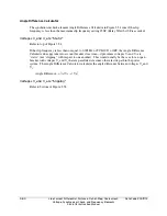
Other SEL
OGIC
control equation torque control settings may be set to provide directional control.
Where potentials are absent at Terminals VA, VB, VC, set 51PTC = 1 to use this element in a
nondirectional mode. See
Overcurrent Directional Control Provided by Torque Control
Settings
at the end of
Section 4: Loss-of-Potential, CCVT Transient Protection, Load-
Encroachment, and Directional Element Logic
.
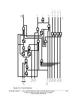
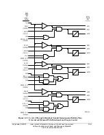
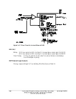
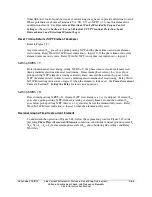
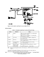
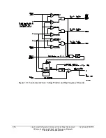
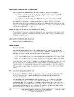
Reset Timing Details (51PT Element Example)
Refer to Figure 3.47.
Any time current I
ABC
goes above pickup setting 51PP and the phase time-overcurrent element
starts timing, Relay Word bit 51PR (reset indication) = logical 0. If the phase time-overcurrent
element times out on its curve, Relay Word bit 51PT (curve time-out indication) = logical 1.
Setting 51PRS = Y
If electromechanical reset timing setting 51PRS = Y, the phase time-overcurrent element reset
timing emulates electromechanical reset timing. If maximum phase current, I
ABC
, goes above
pickup setting 51PP (element is timing or already timed out) and then current I
ABC
goes below
51PP, the element starts to time to reset, emulating electromechanical reset timing. Relay Word
bit 51PR (resetting indication) = logical 1 when the element is fully reset. See
Time-Overcurrent
Curves
in
Section 9: Setting the Relay
for reset curve equations.
Setting 51PRS = N
If reset timing setting 51PRS = N, element 51PT reset timing is a 1-cycle dropout. If current I
ABC
goes above pickup setting 51PP (element is timing or already timed out) and then current I
ABC
goes below pickup setting 51PP, there is a 1-cycle delay before the element fully resets. Relay
Word bit 51PR (reset indication) = logical 1 when the element is fully reset.
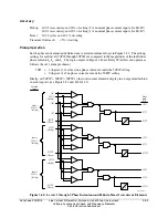
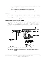
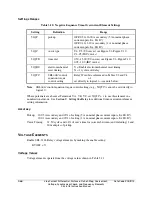
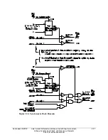
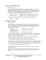
Residual Ground Time-Overcurrent Element
To understand the operation of Figure 3.48, follow the explanation given for Figure 3.47 in the
preceding
Phase Time-Overcurrent Elements
subsection, substituting residual ground current I
G
(I
G
= 3I
0
= I
A
+ I
B
+ I
C
) for maximum phase current I
ABC
and substituting like settings and Relay
Word bits.
Summary of Contents for SEL-311L
Page 6: ......
Page 8: ......
Page 26: ......
Page 54: ......
Page 144: ......
Page 216: ......
Page 252: ......
Page 302: ......
Page 338: ......
Page 480: ......
Page 484: ......
Page 486: ......
Page 502: ......
Page 532: ...12 28 Standard Event Reports and SER Date Code 20010625 SEL 311L Instruction Manual 4 ...
Page 552: ......
Page 554: ......
Page 574: ......
Page 576: ......
Page 596: ......
Page 602: ......
Page 628: ......
Page 656: ......
Page 662: ......
Page 664: ......
Page 688: ......
Page 700: ......
Page 716: ......
Page 722: ......
Page 734: ......