


3-54
Line Current Differential, Distance, Out-of-Step, Overcurrent,
Date Code 20011112
Voltage, Synchronism Check, and Frequency Elements
SEL-311L Instruction Manual
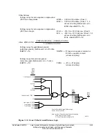
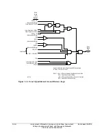
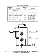
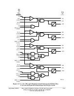
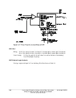
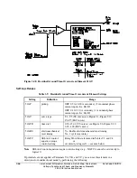
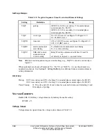
Torque Control
Levels 1 through 3 in Figure 3.42 have corresponding SEL
OGIC
control equation torque control
settings 67P1TC through 67P3TC. SEL
OGIC
control equation torque control settings cannot be
set directly to logical 0. The following are torque control setting examples for Level 1 phase
instantaneous/definite-time overcurrent elements 67P1/67P1T.
67P1TC = 1
Setting 67P1TC set to logical 1:
Then 67P1/67P1T follows 50P1.
Note
: All overcurrent element SEL
OGIC
control equation torque control
settings are set directly to logical 1 (e.g., 67P1TC = 1) for the
factory default settings. See
SHO Command (Show/View Settings)
in
Section 10: Line Current Differential Communications and
Serial Port Communications and Commands
for a list of the
factory default settings.
67P1TC = IN105 Input IN105 deasserted (67P1TC = IN105 = logical 0):
Phase instantaneous/definite-time overcurrent elements 67P1/67P1T are
defeated and nonoperational, regardless of any other setting.
Input IN105 asserted (67P1TC = IN105 = logical 1):
67P1/67P1T follows 50P1.
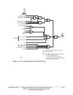
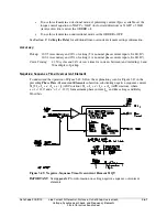
67P1TC = M2P 67P1/67P1T uses the Zone 2 mho phase distance element to provide forward
directional control if potentials are present at Terminals VA, VB, and VC. The
element will be nondirectional if 67P1TC = 1.
Other SEL
OGIC
control equation torque control settings may be set to provide directional control.
See
Overcurrent Directional Control Provided by Torque Control Settings
at the end of
Section 4: Loss-of-Potential, CCVT Transient Detection, Load-Encroachment, and
Directional Element Logic
.
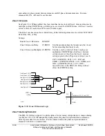
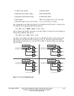
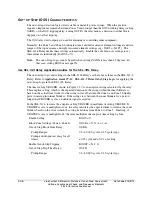
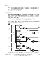
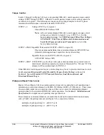
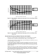
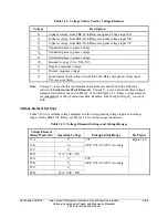
Pickup and Reset Time Curves
Figure 3.43 and Figure 3.44 show pickup and reset time curves applicable to all nondirectional
instantaneous overcurrent elements in the SEL-311L Relay (60 Hz or 50 Hz relays). These times
do not include output contact operating time and, thus, are accurate for determining element
operation time for use in internal SEL
OGIC
control equations. See
Section 1: Introduction and
Specifications
for output contact operating time specifications.
If instantaneous overcurrent elements are made directional (with standard directional elements
such as 32QF), the pickup time curve in Figure 3.43 is adjusted as follows:
multiples of pickup setting
≤
4: add 0.25 cycle
multiples of pickup setting > 4: add 0.50 cycle
Summary of Contents for SEL-311L
Page 6: ......
Page 8: ......
Page 26: ......
Page 54: ......
Page 144: ......
Page 216: ......
Page 252: ......
Page 302: ......
Page 338: ......
Page 480: ......
Page 484: ......
Page 486: ......
Page 502: ......
Page 532: ...12 28 Standard Event Reports and SER Date Code 20010625 SEL 311L Instruction Manual 4 ...
Page 552: ......
Page 554: ......
Page 574: ......
Page 576: ......
Page 596: ......
Page 602: ......
Page 628: ......
Page 656: ......
Page 662: ......
Page 664: ......
Page 688: ......
Page 700: ......
Page 716: ......
Page 722: ......
Page 734: ......